Sixteenth Ordinance on the implementation of the Federal Immission Control Act (Traffic Noise Protection Regulation-16. BImSchV)
Unofficial table of contents
16. BImSchV
Date of completion: 12.06.1990
Full quote:
" Traffic noise protection regulation of 12 June 1990 (BGBl. 1036), as defined by Article 1 of the Regulation of 18 December 2014 (BGBl. 2269).
| Status: |
Amended by Art. 1 V v. 18.12.2014 I 2269 |
For more details, please refer to the menu under
Notes
Footnote
(+ + + Text evidence from: 21.6.1990 + + +)
Unofficial table of contents
Input formula
On the basis of § 43 (1) sentence 1 no. 1 of the Federal Immission Protection Act of 15 March 1974 (BGBl. 721, 1193), the Federal Government shall, after consulting the parties concerned, order:
Unofficial table of contents
§ 1 Scope
(1) The Regulation shall apply to the construction or substantial modification of public roads and railway tracks of the railways and trams (roads and railways). (2) The amendment is essential if:
-
1.
-
a road around one or more continuous traffic lanes for motor vehicle traffic or a rail route around one or more continuous tracks is extended in construction, or
-
2.
-
is increased by at least 3 decibels (A) or at least 70 decibels (A) per day or at least 60 decibels (A) during the night by a significant structural intervention of the assessment level of the traffic noise emitted by the traffic route to be changed.
A change is also essential if the level of assessment of the traffic noise of at least 70 decibels (A) on the day or 60 decibels (A) at night is increased by a significant structural intervention; this shall not apply in commercial areas.
Unofficial table of contents
§ 2 Immission limit values
(1) In order to protect the neighbourhood from harmful environmental effects caused by traffic noise, the construction or the essential modification shall ensure that the assessment level does not exceed one of the following emission limit values:
| |
|
Day |
Night |
| 1. |
at hospitals, schools, health care centres and homes for the elderly |
| |
|
57 Dezibel (A) |
47 Dezibel (A) |
| 2. |
in pure and general residential areas and small settlement areas |
| |
|
59 Dezibel (A) |
49 Dezibel (A) |
| 3. |
in core areas, village areas and mixed areas |
| |
|
64 Dezibel (A) |
54 Dezibel (A) |
| 4. |
in industrial areas |
|
| |
|
69 Dezibel (A) |
59 Dezibel (A) |
(2) The nature of the installations and territories referred to in paragraph 1 shall be the result of the fixing in the land-use plans. Other land set up in development plans for installations and areas and installations and areas for which there are no fixed conditions shall be laid down in accordance with paragraph 1, paragraphs 1, 3 and 4, in accordance with the provisions of paragraph 1, (3) If the use to be protected is exercised only on the day or only during the night, only the immission limit value for this period shall be applied. (4) The Federal Government shall, at the latest in the year 2025 and then continuously every ten years the German Bundestag report on the implementation of the regulation. The report shall indicate in particular whether the emission limit values referred to in Article 2 (1) are in accordance with the state of noise impact research and whether further measures to protect against harmful environmental effects caused by traffic noise are required.
Unofficial table of contents
Section 3 Calculation of the assessment level for roads
The assessment level for roads shall be calculated in accordance with Appendix 1. The calculation has to be done separately for the assessment period (6 a.m. to 10 p.m.) and the assessment period of night (22 o'clock to 6 o'clock).
Unofficial table of contents
Section 4 Calculation of the assessment level for rail routes
(1) The assessment level for rail routes shall be calculated in accordance with Appendix 2. The calculation has to be done separately for the evaluation period (6 a.m. to 10 p.m.) and the assessment period of night (10 p.m. to 6 a.m.). (2) In the calculation, the following conditions must be observed in particular:
-
1.
-
the sound level characteristics of vehicles and driving paths,
-
2.
-
the influences on the propagation path,
-
3.
-
the characteristics of rail transport by means of up-and-down stops
-
a)
-
the length, frequency and frequency of noise, as well as the length and frequency of noise, and
-
b)
-
for the lameness of sound or impulshal noises.
(3) By way of derogation from the first sentence of paragraph 1, sections of projects for which the planning procedure has already been opened up to 31 December 2014 and the interpretation of the plan has been made public, Section 3 in conjunction with Annex 2 shall be published in the shall continue to apply until 31 December 2014. § 43 (1) sentence 3 of the Federal Immission Protection Act remains unaffected.
Unofficial table of contents
§ 5 Setting of acoustic parameters for different railway technology and sound-technical innovations
(1) Differing railway technology or sound technical innovations may be taken into account in the calculation of the assessment level in accordance with Article 4 (1), first sentence, only if the competent authority in a proceeding according to the provisions of paragraphs 2 to 4 for the Calculation has established acoustic characteristics. Deviating railway technology is technology which is not listed in Appendix 2, points 3 to 6, or supplement 1 to 3, and which is to be assigned to one of the following areas:
-
1.
-
Road maps,
-
2.
-
Noise reduction measures on the track or on the wheel or
-
3.
-
railway-specific sound reduction measures in the propagation path.
Technical innovations shall be technical new and further developments to the railway technology listed in Annex 2 (3) to (6) or from 1 to 3, which shall have an impact on the noise emission and emission of this railway technology. (2) Determination of acoustic characteristics decides upon application for the railways of the federal government the Federal Railway Authority and for other railways the authority responsible in each case according to national law. An acoustic characteristic shall be determined if the emission data of the different railway technology or of the sound technical innovations are indicative of this technology and if, in the case of sound technical innovations, the acoustic characteristic values of the Annex 2 (3) to (6) or (1) to (3) of each of the above-mentioned characteristics differ substantially. A significant deviation shall be at least equal to the values set out in Annex 2, point 9.2.2. (3) shall be entitled to submit an application in accordance with the first sentence of paragraph 2,
-
1.
-
railway infrastructure undertakings,
-
2.
-
Holders of the rights of protection of different railway techniques or of sound technical innovations and
-
3.
-
Licensees of different railway techniques or of sound engineering innovations.
(4) The application referred to in the first sentence of paragraph 2 shall contain the following information and documents:
-
1.
-
a description of the divergent railway technology or sound-technical innovation for which the definition of acoustic characteristics is requested, in particular where the different railway technology or sound technical innovation is of the relevant technology listed in Appendix 2;
-
2.
-
the opinion of a recognised measuring point in accordance with Annex 2, point 9.3,
-
3.
-
a proposal on which regulation of Annex 2 (3) to (6) or (1) to (3) may, by way of derogation, be described in addition to a data sheet in the form of a data sheet in which the divergent railway technology may be supplemented or supplemented by a technical innovation, The proposed assignment is the usual acoustic characteristics,
-
4.
-
a description of how the acoustic effectiveness changes due to wear and tear.
(5) The competent authority shall inform the applicant in writing of the decision referred to in the first sentence of paragraph 2. The competent authority shall also publicly disclose the establishment of acoustic characteristics referred to in the first sentence of paragraph 2.
Unofficial table of contents
Final formula
The Federal Council has agreed.
Unofficial table of contents
Appendix 1 (to § 3)
Calculation of the assessment level for roads
Source of the original text: BGBl. I 1990, 1037-1044
The assessment level Lr, T in decibels (A) (dB (A)) for the day (6.00 to 22.00 o'clock) and the assessment level Lr, N in dB (A) for the night (22.00 to 6.00 o'clock) shall be calculated for a lane according to the following equations:

(1)

(2)
It means:
Lm, T
(25) ...
-
-
-
-
-
-
-
Medium level in dB (A) for the day (6.00 to 22.00) according to diagram I.
Lm, N
(25) ...
-
-
-
-
-
-
-
Average level in dB (A) for the night (22.00 to 6.00 o'clock) according to diagram I.
The relevant hourly traffic strength M and the relevant truck component p are calculated using the forecast average daily traffic intensity (DTV) according to Table A on which the planning is based, provided that no suitable project-related results of the project, taking into account the development of traffic during the forecasting period
-
a)
-
the relevant hourly traffic strength M (in motor vehicles/h)
-
b)
-
of the relevant truck share p (over 2.8 tonnes permissible gross vehicle weight) in% of total transport
may be used as an average over all days of the year for the period between 22.00 and 6.00 o'clock. The traffic volume of a road is to be allocated half to the two outer lanes each. The emission type shall be assumed at a height of 0.5 m above the centre of these lanes.
DV ...
-
-
-
-
Correction for different permissible maximum speeds as a function of lorry share p according to diagram II.
DStrO ...
-
-
-
-
Correction for different road surfaces according to Table B.
DStg ...
-
-
-
-
Correction for gradients and gradients according to Table C.
DSDUB ...
-
-
-
-
Level change due to different distances S.sub.g between the emission location (0.5 m above the centre of the lane under consideration) and the relevant immission location without soil and meteorological attenuation according to diagram III. The relevant immission location depends on the circumstances in each individual case; in front of buildings it is located at the height of the floor (0.2 m above the upper edge of the window) of the room to be protected; in the case of exterior living areas, the immission location is 2 m above the centre of the surface area used as an outdoor living area.
DBM ...
-
-
-
-
Level change due to soil and meteorological attenuation as a function of the mean height hm according to diagram IV. The mean height hm is the mean distance between the ground and the connection line between emission and immission location. In the same terrain, hm is the arithmetic mean of the heights of the emission range and of the immission variety above ground,
DB ...
-
-
-
-
Change of level by topographical conditions, constructional measures and reflections. Depending on the local conditions, these are in particular noise protection rolling walls and walls. Incisions, soil elevations and shielding by construction equipment. The level change DB is to be determined in accordance with the guidelines for noise protection in road edition 1990-RLS-90, chapter 4.0, published in the Official Journal of the Federal Minister of Transport of the Federal Republic of Germany (VkBl.) No. 7 of 14. April 1990, under lfd. 79. The guidelines are to be obtained from the Forschungsgesellschaft für roads-und Verkehrswesen, Alfred-Schütte-Allee 10, 5000 Cologne 21.
-
K ...
-
Surcharge for increased disturbing effects of light-sign-controlled intersections and intakes according to Table D.
With the aid of equations (1) and (2), the assessment levels are calculated for long, straight travel strips, which have constant emissions and unaltered propagation conditions over their entire length.
If one of these conditions does not apply, the lanes must be divided into sections whose individual assessment levels are to be determined in accordance with the guidelines for noise protection in road edition 1990-RLS-90, Chapter 4.0, Published in the Official Journal of the Federal Minister for Transport of the Federal Republic of Germany (VkBl.) No. 7 of 14 April 1990 under lfd. 79. The guidelines are to be obtained from the Forschungsgesellschaft für roads-und Verkehrswesen, Alfred-Schütte-Allee 10, 5000 Cologne 21.
The assessment levels of the two outer lanes are to be combined according to diagram V to the overall assessment level for the road.
The overall assessment levels Lr, T and Lr, N are to be rounded up to entire dB (A). In the case of § 1 para. 2 no. 2, only the difference of the assessment level is to be rounded up.
Diagram I: Medium level Lm, T
(25) or Lm, N
(25) in dB (A)
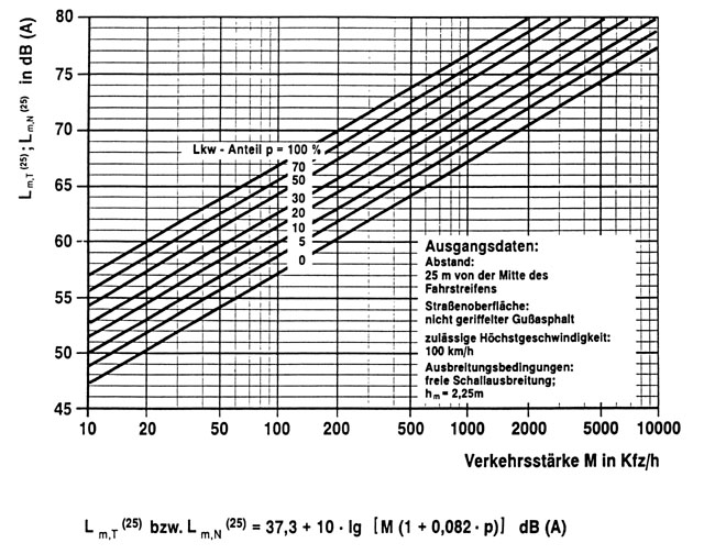
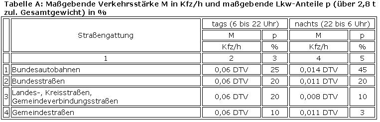
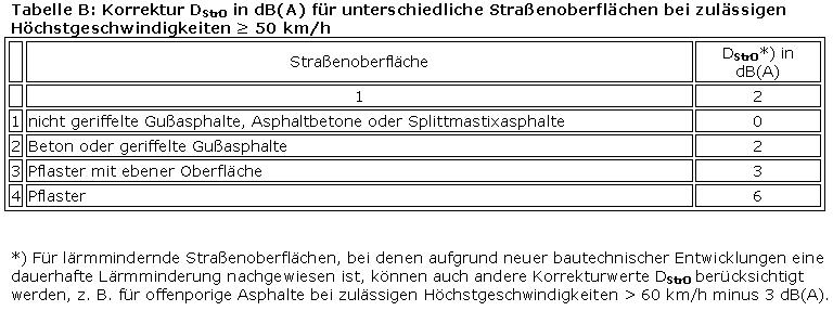
Diagram II: Correction Dv in dB (A) for different permissible maximum speeds as a function of lorry share p
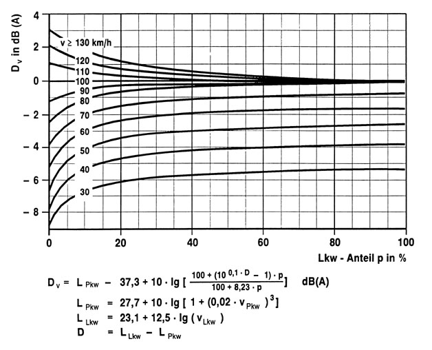
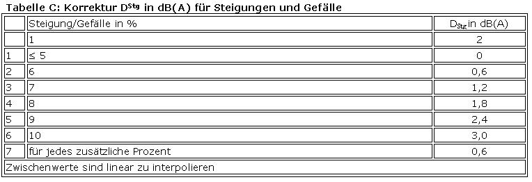
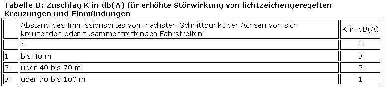
Diagram III: Change in level of DsDR in dB (A) by different distances between the emission location (0.5 m above the centre of the lane under consideration) and the relevant immission location
Diagram IV: Level change DBM in dB (A) due to ground and meteorological attenuation depending on the mean height hm
Diagram V: Overall assessment level Lr, ges from two assessment levels Lr, 1 and Lr, 2
 Unofficial table of contents
Appendix 2 (to § 4)
Calculation of the rating level for rail tracks (Schall 03)
(Fundstelle: BGBl. I 2014 pp. 2271-2313) Table of contents
-
1.
-
Calculation procedure
-
2.
-
Terms, stipulations
-
3.
-
Modelling of sound sources
-
4.
-
Sound emissions from railways
-
5.
-
Sound emissions from trams
-
6.
-
Sound propagation
-
7.
-
Calculation of the formwork emission
-
8.
-
Assessment Level
-
9.
-
Consideration of deviating railway technology and sound-technical innovations
-
10.
-
Accessibility of technical rules and standards
-
1.
-
Calculation procedures For rail paths, the assessment level Lr in the neighbourhood is given separately for the assessment period day (6 a.m. to 10 p.m.) and the assessment period of night (22 p.m. to 6 a.m.) as specified in point 8.1. The basis for the calculation of the assessment level is the number of projected trains of the respective type of train, as well as the underlying speeds on the planning section to be considered for the planning phase. Bahnstrete.On the basis of these forecast data, the calculation of the assessment level shall be carried out in the following steps:
-
-
-
Division of the railway line to be considered into individual tracks and sections. a. with the same transport composition, the same speed, the same type of roadway and the same ground state as specified in point 3.1, and the identification and determination of the sound sources of the Rangier and Transshipment Stations referred to in point 4.8;
-
-
-
on the basis of the quantities per hour nFz of all types Fz of vehicle units, calculation of the length-related or surface level of the sound power in octave bands, separately for each section of a distance referred to in point 3.2 or for each source of sound of a howler and transhipment station in all altitudes h in accordance with point 3.3;
-
-
-
Separation of the sections into sections kS and/or disassembly of the areas in sub-areas kf to form point sound sources with an allocated level of sound power, taking into account the directional effect and the emission characteristics in accordance with points 3.4 and 3.5;
-
-
-
Calculation of the sound emissions of railways as specified in point 4 and supplement 1, respectively Leaflet 3 and of trams referred to in paragraph 5 and supplement 2;
-
-
-
Calculation of the acoustic emission by means of propagation calculation in accordance with point 6;
-
-
-
a summary of the amount of noise emission at the immission site referred to in point 7;
-
-
-
Formation of the assessment level for the relevant assessment periods referred to in point 8.
The software products used for the calculation must ensure the standard-compliant illustration of this rule; this can be done in accordance with DIN 45687, acoustics software products for the calculation of the sound emissions in the open air. Quality requirements and test specifications, May 2006 edition.
-
2.
-
Terms, stipulations
-
2.1
-
Railway technical terms
-
2.1.1
-
Railway vehicles and infrastructure, which are listed in the General Railway Act (AEG); for the delimitation of trams (cf. 2.1.9)
-
2.1.2
-
The smallest part of a railway train or railway train which cannot be dismantled during the driving operation. a tramway vehicle
-
2.1.3
-
Passenger stations, holding points and holding stations where passengers are in, for or out 1: In the case of railroads, the EBO is located between the station (§ 4 paragraph 2 EBO), the holding point (§ 4 paragraph 8 EBO) and the stop (§ 4 Paragraph 9 EBO). In the case of trams, the concept of the bus stop is generally used (§ 31 of the tramway construction and operating system-BOStrab) and the double stop (section 31 (1) (3) BOStrab). In this Appendix the terms are used according to the mode of transport (Railway/Tram). Note 2: In the case of railroads, railway stations may be used with other railway lines, e.g. For example, with loading facilities of car ice trains, combined.
-
2.1.4
-
Railway stations for the carriage of goods, on which freight trains are to be constructed or dismantled to a considerable extent
-
2.1.5
-
Rail damper devices for damping sound emission from rail stews
-
2.1.6
-
Rail-level shielding devices for shielding the sound radiation from rail stews
-
2.1.7
-
Rail track rail track with substructure and superstructure including a overhead line, in accordance with points 2.1.1 and 2.1.9, on which switching emissions are caused by driving operations. Note 1: The sound emissions can be from the rolling noise, aerodynamic noises, aggregate and drive noises of rail vehicles. Note 2: Operating systems from which other sound emissions are based, such as: Substations or converters, maintenance and loading facilities, and washing machines, are not covered by this Regulation.
-
2.1.8
-
Upper structure of the sill, consisting of rails on wood, concrete or steel sleepers in the gravel bed
-
2.1.9
-
Tramway vehicles and infrastructure listed in the Passenger Transport Act (PBefG) and the Road-Rail Construction and Operating Regulations (BOStrab); for the delimitation of railways (cf. 2.1.1), by way of derogation from Section 4 (2) of the PBefG, suspension webs or similar types of special design shall not be regarded as trams within the meaning of this Appendix.
-
2.1.10
-
Road-rail tracks, which are embedded in trams or walking surfaces
-
2.1.11
-
Underground railway lines with bus bars which are independent of their design or location on the entire length of the route from other public traffic and do not have railway crossings (Section 1 (2) of the Railroad Cross Law)
-
2.1.12
-
Intermodal terminals of combined transport as a part of public rail transport with tracks for freight trains moving on and off, with loading means and charging roads connecting to the public road network, where applicable with storage or intermediate storage surfaces
-
2.1.13
-
Composite knock brake pad brakes with brake soles made of composite materials; these brakes use, for example, B. Composite brake shoe soles with high coefficient of friction (K-Sohle) or low coefficient of friction (LL-sole).
-
2.2
-
Sound technical terms
-
2.2.1
-
A-weighted sound pressure level LpA10 times the decadic logarithm of the quotient of the square of the effective value of the sound pressure with the frequency evaluation A together with a time evaluation and the square of the reference sound pressure p0 = 20 μPa in Air Note 1: The frequency rating A and the time evaluation (e.g. B. F, S) are given as the index of the sound pressure level Lp, e.g. B. lpAF.Note 2: The sound pressure level is expressed in decibels, dB.
-
2.2.2
-
A-Rating AFrequency rating according to DIN EN 61672-1, Electro-acoustic sound level meter-Part 1; Requirements, edition October 2003Note: The marking of an A-rated level is carried out according to the standard by the index A at the formula symbol L, not by appending the formula character A to the dB unit.
-
2.2.3
-
Shielding dimensional decrease of the sound pressure level at a location behind an obstacle in relation to the sound pressure level without hindrants in the case of a freely progressing acoustic wave note: The shielding dimension is given in decibels, dB.
-
2.2.4
-
Loss of absorption loss of sound energy in the case of a reflection note: The absorption loss is indicated in decibels, dB.
-
2.2.5
-
Equivalent continuous sound pressure level Lp, Aeq, TA-weighted energy-equivalent mean level for a sound pressure level note variable over time T: The equivalent continuous sound level Lpeq, T (for example for frequency evaluation A and Time evaluation (F) is defined as follows:
 (see also average level) Note: The equivalent continuous sound pressure level is indicated in decibels, dB.
-
2.2.6
-
Assessment level LrSize for marking the strength of the acoustic emission during the assessment period Tr, taking into account the increase or drop in the amount of noise, times or situations; if no increase or drop is taken into account , is the equivalent continuous sound level of the assessment level: Note 1: The assessment level Lr shall be as follows from the equivalent permanent sound level LpAFeq, Ti and the accesses Ki during the part-time intervals Ti for the assessment time Tr Formed:
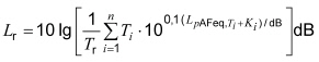 Note 2: The assessment level is expressed in decibels, dB.
-
2.2.7
-
Reference height for sound source SOrail upper edge for rail vehicles, related to the GleisachseFOFahrwegoberEdge for road vehicles, related to the road surface
-
2.2.8
-
Single-event level Lp, T0 = 1sThe equivalent continuous sound pressure level of a SchallereignissesNote 1 occurring in the time period T is equivalent to 1 second:
 Note 2: In octave bands, the A-weighted individual event level is indicated by LEA, ' designnet.Note 3: The single event sound pressure level is expressed in decibels, dB.
-
2.2.9
-
Emission level LmEequivalent continuous sound pressure level according to acoustics 03: guideline for the calculation of the sound emissions of railway tracks-Schall 03, issue 1990, published in the Official Journal of the Deutsche Bundesbahn no. 14 of 4 April 1990 under the lfd. Number 133 for a given period, e.g. B. for the daytime, free sound propagation from an unshielded track/track, depending on the characteristics of the roadway, the ground state and the quantities of train/vehicle, at a distance of 25 m from the track/road axis and at a height of 3.5 m above the Rails/FahrwegoberkanteNote: The emission level can be estimated for flat terrain by LmE = LW 'A -19 dB from the level of the LW' A length-related sound power.
-
2.2.10
-
ImmissionsortIObesposeful place for the determination of a judgment level, according to this Appendix
-
-
-
in the case of buildings at the height of the ceiling (0.2 m above the upper edge of the window) on the façade of the rooms to be protected, and
-
-
-
for outdoor living areas 2 m above the centre of the area used as an outdoor living area
Note: Reflections on the associated facade are not taken into account for immission-type buildings.
-
2.2.11
-
Average level LmDeposit value for the description of sound processes with a temporally varying level or sound fields with locally different sound levels or a combination thereof: The A-weighted average level for a time-variable sound pressure level is called the equivalent continuous sound pressure level.
-
2.2.12
-
Octave in the frequency range of an octave specified sound level
-
2.2.13
-
Level of area A-weighted sound power LW " AA-weighted average level for the description of the sound emission from a surface sound source; specified in this Appendix for the average height of the rails/roadway edges in a Surface area note: the level shall be 1 pW with respect to sound power and 1 m area 2 in decibels, dB.
-
2.2.14
-
Length of A-weighted sound power LW ' AA-weighted average level for the description of the sound emission from a line sound source; specified in this Appendix for different altitudes over a section of road or road surface with certain road characteristics and surface conditions during operation with certain vehicles and speed note: the level is indicated with respect to a sound power of 1 pW and a length of 1 m in decibels, dB.
-
2.2.15
-
Level correction for the conspicuity of noise level correction in order to take into account the increased conspicuity of noises with pronounced pitch, impulse or information note: The level correction for the conspicuity of the noise level of the noise level of the noise level correction Noises are indicated in decibels, dB.
-
2.2.16
-
Level corrections for noises of bridges and viaducts without sound protection KBrLevel corrections to take account of wheel-and rail-related rolling noise when driving via bridges and viaducts without sound protection Note 1: This level correction also includes the disturbing effect of low-frequency noise components, which are not adequately taken into account by the A-rating of the sound level. Note 2: As a viaduct, a bridge with several fields is named in this facility. Note 3: The level corrections for noises of bridges and viaducts will be Decibels, dB, specified.
-
2.2.17
-
Level corrections for noises of bridges and viaducts with sound protection KBr + KLMPegelcorrections in order to take account of wheel and rail-related rolling noise when driving via bridges with sound protection Note 1: The separate expulsion of the The effect of sound reduction measures is used to encourage the use of low-emission bridge constructions.Note 2: The level corrections for noises of bridges and viaducts with sound protection are given in decibels, dB.
-
2.2.18
-
Level Correction Road-SchieneKSPegel correction to take into account the lower interference effect of rail traffic noise in relation to road noise Note 1: The application of the level correction has been made in § 3 in conjunction with Appendix 2 of the Traffic noise protection regulation of 12 June 1990 (BGBl. 1036) and by the Eleventh Law amending the Federal Immission Control Act of 2 July 2013 (BGBl. I p. 1943) with effect from 1 January 2015 for railways and on 1 January 2019 for trams (cf. § 43 (2) sentences 2 and 3 of the Federal Immission Protection Act). Note 2: The level correction road rail is indicated in decibels, dB.
-
2.2.19
-
Measurement scale for the description of the non-uniform emission of a sound source in the air; according to this system, uniform for all sound sources of a distance in all frequency bands Note: The directivity measure is in decibels, dB, specified.
-
2.2.20
-
Sound absorption conversion of sound energy from a room or room area in thermal remark: The sound absorption is expressed in decibels, dB.
-
2.2.21
-
Sonic pressure level LpTen times the logarithm of the quotient of the square of the sound pressure p and the square of the reference sound pressure p0 = 20 µ PaNote: The sound pressure level is expressed in decibels, dB.
-
2.2.22
-
Sound emission of sound
-
2.2.23
-
Noise emission performance of sound at the immission location
-
2.2.24
-
Sound power level for the description of the sound emission of a single sound source note: The sound power level is given in decibels, dB, with respect to sound power of 1 pW.
-
2.2.25
-
Sound reflectance reflectance fraction of the acoustic energy, based on the incident sound energy, for a given frequency and defined conditions of a reflecting surface
-
2.3
-
Formula characters, Units, Meter Table 1: Formula characters, units and meaning
SpalteABC
Time Formula character unit meaning
| 1 |
A |
dB |
A-assessed total level of the length-related sound power under certain conditions |
| 2 |
Delta |
dB |
Difference to the total level of A in the octave band |
| 3 |
A |
dB |
Propagation damping measure |
| 4 |
Adiv |
dB |
Damping measure due to geometric propagation |
| 5 |
Aatm |
dB |
Damping measure due to air absorption |
| 6 |
Agr |
dB |
Damping measure as a result of soil influence |
| 7 |
Abar |
dB |
Damping measure due to shielding by obstacles |
| 8 |
B |
- |
Speed factor |
| 9 |
C |
dB |
Counter for level corrections c1 and c2 |
| 10 |
c1 |
dB |
Level correction for roadway types |
| 11 |
c2 |
dB |
Level correction for surface condition |
| 12 |
C2 |
- |
Shielding factor for single diffraction |
| 13 |
C3 |
- |
Additional shielding factor for multiple diffraction |
| 14 |
d |
M |
Length of sound of sound between sound source and immission location |
| 15 |
Dp |
M |
Horizontal distance between sound source and immission location |
| 16 |
dr |
M |
Distance Last Diffraction Edge-Immission Location |
| 17 |
ds |
M |
Distance sound source-1. Diffraction Edge |
| 18 |
Dso |
M |
Distance sound source-Reflector |
| 19 |
dor |
M |
Distance reflector-immission location |
| 20 |
dusers |
M |
Distance sound source-Immission location parallel to the diffraction edge |
| 21 |
DI |
dB |
Direction Measure |
| 22 |
DIr |
dB |
Directional measure of the reflected sound |
| 23 |
Dreƒl |
dB |
Level correction for reflective soundproofing wall with absorbent base |
| 24 |
Dz |
dB |
Shielding Measure |
| 25 |
Dρ |
dB |
Reflectance Measure |
| 26 |
DΩ |
dB |
Spatial angle measure |
| 27 |
e, e1 ... |
M |
Distance between Diffraction Edges |
| 28 |
T |
- |
Octavband Counter |
| 29 |
M |
- |
Octave bandmite frequency |
| 30 |
Fz |
- |
Vehicle Category Count |
| 31 |
h |
- |
Elevation Count |
| 32 |
habs |
M |
Height of the absorbent base of a soundproofing wall |
| 33 |
hg |
M |
Height of the sound source above the ground |
| 34 |
hLSW |
M |
Mean height of a soundproofing wall above the top edge of the rail |
| 35 |
hm |
M |
Medium height above ground |
| 36 |
h |
M |
Height of the sound source above the rail top edge |
| 37 |
Hr |
M |
Height of the immission variety above the ground |
| 38 |
I |
- |
Single Sound Source Count |
| 39 |
Y |
- |
Line Source Count |
| 40 |
K |
dB |
Counter for level corrections K |
| 41 |
C |
dB |
Level fixes |
| 42 |
KBr |
dB |
Level Correction for Bridges |
| 43 |
kF |
- |
Part of an area count |
| 44 |
KLM |
dB |
Level correction for sound reduction measures on bridges |
| 45 |
KL |
dB |
Level correction for the abnormality of noise |
| 46 |
KLA |
dB |
Level correction for noise protection measures against the abnormality of noise |
| 47 |
Kmet |
- |
Correction factor for meteorological influences |
| 48 |
kS |
- |
Counter for part of a line or Route |
| 49 |
KS |
dB |
Level correction to take into account the lower interference effect of rail traffic noise |
| 50 |
I |
M |
Length |
| 51 |
lh |
M |
Horizontal measurement of an obstacle on the sound propagation path |
| 52 |
11 |
M |
Vertical distance between connecting line source-receiver and 1. End point of the obstacle on the sound propagation path |
| 53 |
lr |
M |
Vertical distance between connecting line source-receiver and second end point of the obstacle on the sound propagation path |
| 54 |
lmin |
M |
Smallest dimension of the reflector |
| 55 |
LEA |
dB |
A-weighted single event level per octave band |
| 56 |
Lp, Aeq |
dB |
Equivalent continuous sound pressure level |
| 57 |
Lp, Aeq, day |
dB |
Equivalent continuous sound pressure level for the evaluation period (6 am to 10 pm) |
| 58 |
Lp, Aeq, Night |
dB |
Equivalent continuous sound pressure level for the night assessment period (10 p.m. to 6 a.m.) |
| 59 |
Lr |
dB |
Assessment Level |
| 60 |
LWA |
dB |
A-weighted total sound power level |
| 61 |
ΔLW, |
dB |
Level difference to the A-weighted total sound power level in the octave band |
| 62 |
LW ' A |
dB |
A-weighted overall level of the length-related sound power |
| 63 |
LW " A |
dB |
A-assessed total level of area-related sound power |
| 64 |
ΔLW ',' |
dB |
Level difference to the A-weighted total level of the length-related sound power in the octave band |
| 65 |
LWA, in |
dB |
A-weighted total sound power level of the mirror sound source |
| 66 |
M |
- |
Partial source number |
| 67 |
nAchs |
- |
Number of axles per vehicle unit |
| 68 |
nFz |
- |
Number of vehicles per hour |
| 69 |
Ni |
- |
Number of events per hour at the point source |
| 70 |
nj |
- |
Number of events per hour at the line sound source |
| 71 |
nQ |
- |
Number of sound sources per vehicle unit |
| 72 |
q |
- |
Number of sound sources in the rangion and transhipment station |
| 73 |
R |
M |
Radius |
| 74 |
R |
- |
Index for shunting station |
| 75 |
S |
M 2 |
Area |
| 76 |
T |
R |
Duration |
| 77 |
C |
km/h |
Speed |
| 78 |
W |
- |
Propagation path count |
| 79 |
T |
M |
Umweg of a sound beam by diffraction |
| 80 |
α |
dB/km |
Absorption coefficient |
| 81 |
β |
Wheel |
Reflection Angle |
| 82 |
The |
Wheel |
Sound radiation angle |
| 83 |
λ |
M |
Sound wave length |
| 84 |
ρ |
- |
Sound reflectivity |
Table 2: Abbreviations
SpalteAB
Time Abbreviation
| 1 |
büG |
particularly monitored track |
| 2 |
E-Lok |
Electric locomotive |
| 3 |
ET |
Electric railcars |
| 4 |
FO |
Roadway Edge |
| 5 |
HGV |
High speed transport |
| 6 |
IO |
Immission location |
| 7 |
Rbf |
Rangiers Train Station |
| 8 |
SO |
Rail top edge |
| 9 |
Ubf |
Terminal station |
| 10 |
V-Lok |
Combustion locomotive (diesel locomotive) |
| 11 |
VT |
Combustion striker |
-
3.
-
Modelling of sound sources
-
3.1
-
Division into sections of uniform sound emission to be assessed shall be divided into sections with a uniform sound emission according to the following criteria:
-
-
-
transport composition,
-
-
-
speed classes,
-
-
-
the type of road,
-
-
-
surface condition,
-
-
-
Station areas and stops,
-
-
-
bridges and viaducts,
-
-
-
Railway crossings,
-
-
-
Curve radii.
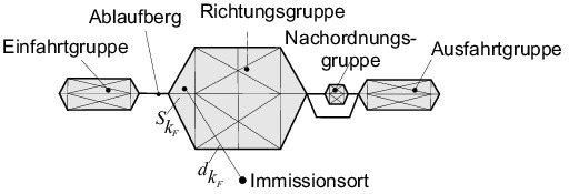
For the sections thus produced, uniform levels of the length-related sound power are to be determined. Rangier and transshipment stations to be assessed are described by sound sources according to Table 10. The respective position of the sound source is indicated in accordance with its geometric extent as a point or line sound source with the corresponding source height according to Table 10 in Cartesian coordinates. Areas of the Rangier or A transfer station with several different sound sources of a height range, but with uniform sound emission, can be combined to form larger surface sound sources. The distribution of shunting and transhipment stations in surface sound sources shall be governed by similar plant parts and operational sequences on the respective surface, which shall be described in a uniform manner by a level of the area-related sound power Railway or tramway lines passing by tenderers and transhipment stations are treated like other routes (see point 2.2.18).
-
3.2
-
Sound power level for railway and tramway level The level of the length-related sound power LW 'A,' A, ', h, m, Fz in the octave band', in the height range h, as a result of a part sound source m (see Table 5 and Table 13), for a vehicle unit of the Vehicle category Fz per hour is based on the following equation (Gl. 1) calculated:
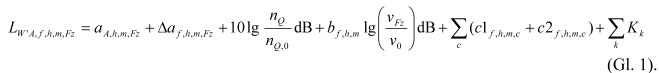 In this case:
| A, h, m, Fz |
A-assessed total level of the length-related sound power at
the reference speed v0 = 100 km/h on a sleeper track with an average surface condition, according to the supplement 1 and 2, in dB, |
| Δια, h, m, Fz |
Level difference in octave band, according to supplement 1 and 2, in dB, |
| nQ |
Number of sound sources of the vehicle unit according to point 4.1 or 5.1, |
| nQ, 0 |
Reference number of the sound sources of the vehicle unit according to point 4.1 or 5.1, |
| b, h, m |
Speed factor according to Table 6 or 14, |
| vFz |
Speed according to point 4.3 or 5.3.2, in km/h, |
| v0 |
Reference speed, v0 = 100 km/h, |
 |
Sum of the c level corrections for road type (c1) according to Table 7 or 15 and driving surface (c2) according to Table 8, in dB, |
 |
Sum of the k level corrections for bridges according to Table 9 or 16 and the abnormality of noise according to Table 11, in dB. |
Note: The indices h, m and Fz are not carried out in supplement 1 and 2. In the calculations, the eight octave bands with the center frequencies of 63 Hz to 8 000 Hz are taken into account. The parameters to be used are set out in point 4 for railways and in point 5 for trams. In the case of traffic of nFz vehicle units per hour of the type Fz, the level of the length-related sound power shall be in the octave band, and Height h according to the following equation (Gl. 2) calculated:

-
3.3
-
Sound power level for Rangier and transshipment stations Sound emission is indicated in eight octave bands at center frequencies from 63 Hz to 8 000 Hz as sound power level for radiation to the spatial angle 4π. The spatial angle measure according to the equation (Gl. 9). Sound sources according to Table 10 are to be distinguished. The sources are shaped in a punctiform or linear form. The level of the A-weighted sound power of point sound sources LW,f, h, i in the octave band, in the height range h, as a result of a single source i, is dependent on the number ni of the events or, respectively, of the events. Units per hour according to the following equation (Gl. 3) calculated:
 The level of the A-weighted sound power of line sound sources LW 'A, ` `, h, j in the octave band', in the height range h, as a result of a single source j, is dependent on the number nj of the events or, respectively, of the events, respectively. Units per hour according to the following equation (Gl. 4) calculated:
 In this case:
| LWA,h, i, LW ' A, h, j |
A-weighted total sound power level, or the length-related sound power of the individual source i or j according to supplement 3, in dB, |
| ΔLW,u, h, i, ΔLW ', j, h, j |
Level difference in the octave band according to supplement 3, in dB, |
| ni, nj |
Number of events or units per hour, |
| Kk |
Level correction for the abnormality of the noises according to Table 9 and Table 11, in dB. |
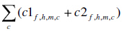
Note: The indices h, i and j are not carried out in the supplement 3. Faces of Rangier and Envelope Stations with a uniform sound emission can be combined to form surface sound sources. The emission of the surface sound source, combined from point and line sound sources, is determined by its A-weighted sound power level LW "A,", "h in the octave band" and the height range h according to the following equation (Gl. 5):
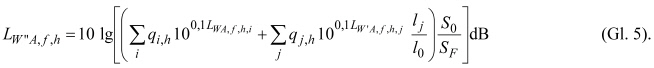 In this case:
| SF |
Face with uniform sound emission, in m 2 , |
| S0 = 1 m 2 |
Reference surface, |
| lj |
Length of line source j, in m, |
| l0 = 1 m |
Reference length, |
| qi, h |
Number of point sound sources of type i in height h, |
| qj, h |
Number of line sound sources of type j in height h. |
Driving movements of trains travelling on, off, and passing by, as well as manoeuvrability, shall be taken into account in accordance with point 3.2.
-
3.4
-
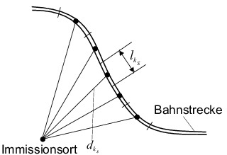
The calculation of the assessment level is based on point sound sources. For this purpose, all lines and areal sources are broken down into point sound sources (see Figure 1). An extended source, for which uniform sound propagation conditions prevail from all parts up to an immission location, is modeled as a point sound source. In addition, the length of the parts is lk or lk, respectively. to limit the size of the SkF face by further disassembly in such a way that, in the event of a half-finish of all sections, Faces of the immission portion according to the equation (Gl. 29) for all contributions at the respective immission location is changed by less than 0.1 dB.
Figure 1: Examples of the breakdown of line and area sound sources into sections and subsurface note 1: In marshalling yards, for example: Note 2: The requirement for uniform propagation conditions at each point of a section considered to be the immission location is specified by the threshold value of 0.1 dB. It includes requirements for distances, sound beam height above the ground, shielding and reflections. As a guide value for a suitable length lks with free sound propagation over the same ground, half of the path length dkS is used from the middle of the part to the immission location. A quarter of the square of the path length dkF from the middle of the partial surface to the immissionsort.From the length lkS of a piece ks and from the length lkS of a partial piece of SkF and from the middle of the partial surface, the distance is equal to the distance of the surface. A-weighted levels of the length-related Oktav sound power LW 'A,', h according to the equation (Gl. 5) in the height ranges h defined according to this Appendix (see Table 5, respectively). Table 10) in this section, the A-weighted sound power levels LWA, ` `, h, kS in the octave band ' are determined in accordance with the following equation (Gl. 6) calculated:
 with l0 = 1 m.Oktav-sound power level according to the equation (Gl. 6) describe together with the directivity measure according to the equation (Gl. 8) and the space-angle measure according to the equation (Gl. 9) the sound emission, with which from a point sound source in the middle of a part ks in height hs above the top edge of the rail. With the surface SkF of a face and from the levels LW "A,", h the area-related sound power according to the equation (Gl. 5) in the height ranges h defined in accordance with Table 10, the sound power levels LWA, ` `, h, kF are determined in accordance with the following equation (Gl. 7) calculated:
 with S0 = 1 m 2 .The Oktav sound power level according to the equation (Gl. 7) describes together with the spatial angle measure according to the equation (Gl. 9) the undirected sound emission of a point sound source in the middle of a face kF in height hs above the rails or rails. the roadway's edge.
-
3.5
-
Directional effect and spatial angle measurement
-
3.5.1
-
Direction effect The directivity measure DI, kS is used in accordance with the following equation (Gl. 8) for sections of route sections:
 In this case, δkS denotes the angle between a sound beam emanating from the point sound source and the track axis (see FIG. 2):
 Figure 2: Definition of the angle δkS on a rail stretch note: The directivity measure is shown graphically in Fig. 3:
 Figure 3: Indicative measure DI, kS in dB according to equation (Gl. 8) for δkS in GradNote 1: The directivity measure characterizes the mean emission of the rolling noise during train journeys in both directions. For sources in Rangier and Transshipment Stations, no directionality will be taken into account in accordance with this calculation rule.
-
3.5.2
-
Spatial angle measurement The sound power levels of all the sources of this system indicate the radiation to the spatial angle 4π. In this case, the apparent increase in the sound power level of the sound source due to reflections on the ground is determined by the space-angle measure according to the following equation (Gl. 9) taken into account:
 In this case:
-
hg
-
the height of the sound source above the ground, in m,
-
Hr
-
the height of the immission area above the ground, in m,
-
Dp
-
horizontal distance between the sound source and the immission location, in m.
Note: Information on the sound source height according to Tables 5, 10 and 13 refer to the roadway's edge. Accordingly, the height of the roadway edge above the ground is to be added to the indicated sound source height.
-
4.
-
Sound emissions from railways
-
4.1
-
For the calculation of the acoustic emission, vehicle categories Fz according to Table 3 are distinguished: Table 3: Vehicle garden, Fz categories and reference number of axles for railways
SpalteABC
Time Car Vehicle Category FzReference Number of the axles nAchs, 0
| 1 |
HGV Engine |
1 |
4 |
| 2 |
HGV mid/control car, not powered |
2 |
4 |
| 3 |
HGV train |
3 |
32 |
| 4 |
HGV-Neigezug |
4 |
28 |
| 5 |
E-train and suburban train (ET) |
5 |
10 |
| 6 |
V-train (VT) |
6 |
6 |
| 7 |
Electrolok (E-Lok) |
7 |
4 |
| 8 |
Diesel locomotive (V-Lok) |
8 |
4 |
| 9 |
Passenger cars |
9 |
4 |
| 10 |
Freight wagons |
10 |
4 |
Definition to table 3, column C:The sound power of the rolling noise increases with the number of axles. If the number of axles of a vehicle unit deviates from the reference number of the axes nAchs, 0, a correction is made in the equation (Gl. 1) with nQ = nachs. This correction shall be applied only for the sound source type rolling noise according to Table 5. For all other sound source types nQ = nQ, 0. The A-weighted total level A, h, m, Fz of the length-related sound power and the level difference Δφ, h, m, Fz in the octave band at the reference speed v0 = 100 km/h on a threshold level with average surface condition are for each type of vehicle in supplement 1 (see also equation Gl. 1). The composition and the number of vehicle units of trains, provided that they are not specified for the calculation, can be taken from Table 4. Table 4: Transport data for railways
SpalteABCDEFGHIJKL
Time at top speed in regular traffic in km/hNumber of vehicle units per Fz category
12345678910
| 1 |
ICE-1 train |
250 |
2 |
12 |
|
|
|
|
|
|
|
|
| 2 |
ICE-2 half-train |
250 |
1 |
7 |
|
|
|
|
|
|
|
|
| 3 |
ICE-2 enforcement |
250 |
2 |
14 |
|
|
|
|
|
|
|
|
| 4 |
ICE-3 half-train |
300 |
|
|
1 |
|
|
|
|
|
|
|
| 5 |
ICE-3 full train |
300 |
|
|
2 |
|
|
|
|
|
|
|
| 6 |
ICE-T |
230 |
|
|
|
1 |
|
|
|
|
|
|
| 7 |
Thalys-PBKA half-train |
300 |
2 |
5 |
|
|
|
|
|
|
|
|
| 8 |
Thalys-PBKA-Vollzug |
300 |
4 |
10 |
|
|
|
|
|
|
|
|
| 9 |
ETR 470 Cisalpino |
200 |
|
|
|
1 |
|
|
|
|
|
|
| 10 |
IC train (bespted with
E-Lok) |
200 |
|
|
|
|
|
|
1 |
|
12 |
|
| 11 |
IC train (bespted with
V-Lok) |
160 |
|
|
|
|
|
|
|
1 |
12 |
|
| 12 |
Local train
(covered with e-locomotive) |
160 |
|
|
|
|
|
|
1 |
|
5 |
|
| 13 |
Local train
(covered with V-Lok) |
140 |
|
|
|
|
|
|
|
1 |
5 |
|
| 14 |
Local train (ET) |
140 |
|
|
|
|
1 |
|
|
|
|
|
| 15 |
Local train (VT) |
120 |
|
|
|
|
|
1 |
|
|
|
|
| 16 |
IC3 |
180 |
|
|
|
|
|
1 |
|
|
|
|
| 17 |
S-Bahn |
120 |
|
|
|
|
1 |
|
|
|
|
|
| 18 |
Freight train (bespted with
E-Lok) |
100 |
|
|
|
|
|
|
1 |
|
|
24 |
| 19 |
Freight train (bespted with
V-Lok) |
100 |
|
|
|
|
|
|
|
1 |
|
24 |
Notes to Table 4: Line 6: The 7-part version (BR 411) and the 5-part version (BR 415) of the ICE-T are not technically different. Lines 10 and 11: Wheel sets of the carriages with shaft disc brakes. Construction series see data sheet of the vehicle category 5.row 15: detailed regulation according to model series see data sheet of the vehicle category 6.Line 16: To be treated like BR 612 in the data sheet of the vehicle category 6.For freight trains, it can be expected that up to 80 percent by 2020 and 100 percent of freight cars by 2030 Composite knock brakes are equipped. This applies to freight wagons according to lines 5 to 7 and 18 to 20 of supplement 1, vehicle category 10.
-
4.2
-
Sound source species For the calculation of the sound emission, the four sound source types listed in Table 5 are taken into consideration in the associated height ranges. Table 5: Sound source types on vehicles for railways
SpalteABCDE
ZeileSchallsourceartHöhenbereich hheight hs via SOPart sources mSound cause, Component
| 1 |
Rolling noises |
1 |
0 m |
1 |
Rail roughness |
| 2 |
1 |
0 m |
2 |
Radraudity |
| 3 |
2 |
4 m |
3 |
Radiation of the rolling noise transmitted as a body sound due to the roughness of the rail by means of tank wagons. |
| 4 |
2 |
4 m |
4 |
Emission of the rolling noise transmitted as a body-borne sound due to the roughness of the wheel by means of boiler superstructures |
| 5 |
Aerodynamic noises |
3 |
5 m |
5 |
Pantograph |
| 6 |
2 |
4 m |
6 |
Current collector foot, grid of cooling and air-conditioning systems in the roof area |
| 7 |
1 |
0 m |
7 |
Rotation of the bogie |
| 8 |
Aggregate noise |
2 |
4 m |
8 |
Ventilators of cooling and air-conditioning systems, suction side in the roof area |
| 9 |
1 |
0 m |
9 |
Ventilators of cooling and air conditioning systems, suction and pressure sides in the underfloor area |
| 10 |
Drive noise |
2 |
4 m |
10 |
Exhaust system |
| 11 |
1 |
0 m |
11 |
Motor, gearbox |
Definitions in Table 5: Lines 1 and 2: For freight trains with a slope ≥ 20% and a length of ≥ 500 m, a supplement of 3 dB to the rolling noise at the height of hs = 0 m for freight trains with grey cast iron engine brakes on the downhill track is equal to 3 dB. due to braking noises. Lines 3 and 4: In the case of tank wagons, the roughness of the rolling noises due to the sound radiation of the superstructures is also at the height hs = 4 m. The corresponding sub-source is only used for tank wagons. If not more accurately known, a share of 20 per cent tank wagons will be accepted for each freight train.
-
4.3
-
Speed The A-rated total level of the length-related sound power listed in supplement 1 shall apply to the reference speed v0 = 100 km/h. The influence of deviating velocities is found in the equation (Gl. 1) taking into account the speed factor b according to Table 6. Table 6: Speed factor b for railways
SpalteABC
Time Sound Source Part- source mSpeed factor b in the Octave band center frequency, in Hz
| 1 |
|
|
63 |
125 |
250 |
500 |
1 000 |
2 000 |
4 000 |
8 000 |
| 2 |
Rolling noises |
1, 2, 3, 4 |
-5 |
-5 |
-5 |
0 |
10 |
25 |
25 |
25 |
| 3 |
Aerodynamic noises |
5, 6, 7 |
50 |
| 4 |
Aggregate noise |
8, 9 |
-10 |
| 5 |
Drive noise |
10, 11 |
20 |
The speed vFz is determined as follows: The starting point is the maximum permissible vehicle speed in regular traffic. If several vehicles of a train have different maximum speeds, the maximum speed of the slowest vehicle is to be used for all vehicles. If the speed of the track is lower, it is to be used. In the area of passenger stations (within the entry signals) and of stops and/or stops, it is possible to use the following information: Stops (track length plus 100 m on each side) is the permissible speed of the free distance, but at least 70 km/h. With vFz = 70 km/h, they are located in stations and at stops or stops, respectively. sounds occurring in stops areas, such as Note: A compilation of maximum speeds for different gardening can be taken from Table 4.
-
4.4
-
Route maps, railway overgoings The acoustic characteristics listed in supplement 1 shall apply to the swelling of the sleeper (see point 2.1.8). For other types of carriageway, the equation (Gl. 1) Level corrections according to Table 7. Table 7: Level corrections c1 for roadway types
SpalteABC
Time influence level corrections c1 in dB for octave band center frequency, in Hz
631252505001 0002 0004 0008 000
| 1 |
Fixed carrierway |
Increased rail radiation |
0 |
0 |
0 |
7 |
3 |
0 |
0 |
0 |
| 2 |
Reflection on the road |
1 |
1 |
1 |
1 |
1 |
1 |
1 |
1 |
| 3 |
Fixed carrierway
with absorbers |
Increased rail radiation |
0 |
0 |
0 |
7 |
3 |
0 |
0 |
0 |
| 4 |
Reflection on the road |
0 |
0 |
0 |
-2 |
-2 |
-3 |
0 |
0 |
| 5 |
Railway crossing |
Increased rail roughness |
0 |
0 |
0 |
8 |
4 |
0 |
0 |
0 |
| 6 |
Reflection on the road |
1 |
1 |
1 |
1 |
1 |
1 |
1 |
1 |
Definitions in Table 7: Lines 1 and 3: Level correction for the increased sound emission of the rail due to the elastic rail fastening required for fixed roadways; the correction is due to rolling noise due to rail roughness and Radraudity (subsources 1 and 2). For all other subsources m, c1 = 0 dB. Lines 2, 4 and 6: level correction for the altered sound radiation due to the altered reflections in relation to the gravel bed; the correction is to be applied to all sub-sources at the level of the rail (subsources 1, 2, 7, 9 and 11). For all other subsources m, c1 = 0 dB. Lines 3 and 4: Absorbers are to be incorporated as a sound protection measure. Line 5: Level correction for the sound emission of the rail due to the increased road roughness. The correction shall be applied to rolling noise due to the roughness of the rail and the roughness of the wheel (subsources 1 and 2). For all other subsources m, c1 = 0 dB. Lines 5 and 6: The level correction for railway crossings is to be used for sections corresponding to 2 times the road width. Level corrections for other types of road are not to be taken into consideration. Note 1: Swelling of the bulkhead bed includes concrete sleepers, wooden sleepers and steel sleepers. Note 2: In the area of switches, there is usually no Note 3: On a level correction for railway crossings, which are used only as foot and wheel paths, after line 5 completely, after line 6 with a path width of the fixed path crossing of ≤ 7 m, can be dispensed with.
-
4.5
-
Sound-reduction techniques on track The acoustic characteristics listed in supplement 1 apply to an average surface condition and without special acoustic measures on the rail. For the "particularly monitored track (büG)" for the surface state and for measures on the rail webs, according to the equation (Gl. 1) Level corrections according to Table 8. Table 8: Level corrections c2 for the surface condition "particularly monitored track (büG)" as well as for rail shock absorbers and shields
SpalteABC
Time Measure Subsource mLevel corrections c2 in dB in the Octave band center frequency, in Hz
631252505001 0002 0004 0008 000
| 1 |
particularly monitored track (büG) |
1, 3 |
0 |
0 |
0 |
-4 |
-5 |
-5 |
-4 |
0 |
| 2 |
Rail damper |
1, 3 |
0 |
0 |
0 |
-2 |
-3 |
-3 |
0 |
0 |
| 3 |
2, 4 |
0 |
0 |
0 |
-1 |
-3 |
-2 |
0 |
0 |
| 4 |
Rail shield |
1 |
0 |
0 |
0 |
-3 |
-4 |
-5 |
0 |
0 |
The correction values c2 for the "büG" to the partial sources of rolling noise due to the roughness of the rail, sub-sources 1 and 3, in the case of the influencing variables rail shock absorbers to the partial sources 1 to 4 and in the case of the rail shield shielding are only applied to the partial sources of rolling noise, which are the only possible means for the control of the rail traffic. Partial source 1 set. For all other subsources, c2 = 0 dB. The measures set out in Table 8 shall be considered as a sound protection measure. The rail shock absorbers and shields used must have the acoustic effectiveness in accordance with Table 8. An addition of the correction values c2 from the lines 1 and 2 as well as the lines 1 and 4 is possible. Note 1: The "particularly monitored track (büG)" is a sound protection measure with a special form of monitoring and maintenance of the rail travel surfaces. It is based on the knowledge that, in addition to the vehicle-dependent state of the wheel running surfaces, above all the running surface condition of the rails plays a decisive role in the formation of the rolling noise. When this measure is used, certain track sections are checked at regular intervals to their acoustic state and, if necessary, are ground with a special grinding process (acoustic grinding). The aim of the measure is to ensure that such track sections always have an above-average level of good, d. h. the smooth running surface condition of the rails is present and the rolling noise is correspondingly low. Note 2: Rail damper is a damping measure, rail shield shielding is a shielding measure for rail foot and rail web; both Technologies are sound-protection measures. The measure "büG" is connected with the following provisions:
-
-
-
Prior to the commissioning of section sections with the measure "büG" and after each acoustic grinding, the track shall be deemed to have been removed if it is available with the methods recognized for the büG-loops Pr.1110 Rap/Rau 98 of 16.3.1998 (VkBl. 1998, Issue 7, p. 262, lfd. 74).
-
-
-
The sound monitoring of the "büG" is carried out by an experience with the sound measuring carriage (SMW). The first experience shall be carried out no later than twelve months after the commissioning of the route section with the measure "büG". Any further experience with the SMW shall take place no later than twelve months after the previous experience.
-
-
-
If the SMW for a track section shows a measurement value of + 2 dB (trigger threshold) or more, this track section will be acoustically ground within the next twelve months after the experience. An acoustic loop shall not be required if the track section is not longer than 50 m and the trigger threshold is not exceeded on the track sections of at least 200 m in length adjacent to or on either side of the track or on both sides of the track section. the measure "büG" is not carried out there.
-
-
-
The acoustic grinding can be omitted if suitable grinding methods such as e.g. B. High-speed grinding is shown to show that the measured value indicated by the SMW is less than + 1 dB.
In accordance with Section 5 (3), second sentence, further provisions of the competent authority shall be taken into account.
-
4.6
-
When crossing a train via a bridge, the acoustic emission of the bridge superstructure must be taken into account by means of a correction, which also contains the annoyance due to low-frequency noise components. It is represented as a combined bridge and roadway correction KBr, since it also contains the influence of the road on the bridge, in addition to the sound emission of the bridge. Measures which lead to a reduction of the sound emission of a bridge are taken into account by a correction KLM and are to be used as a sound protection measure. For the most common five types of bridges and superstructures, level corrections are given in Table 9. The correction takes place for the clear width of the bridge, plus 2 m on each side. The level corrections apply to the sub-sources 1 and 2. KBr + KLM = 0 dB for all other subsources. Corrections for types of carriageway according to Table 7, lines 1 to 4, shall not be applied. Table 9: Corrections KBr and KLM for bridges
SpalteABC
Zeilebridges-and FahrbahnartKBr in dBKLM in dB
| 1 |
Bridges with steel superstructure, track directly mounted |
12 |
-6 |
| 2 |
Bridges with steel superstructure and swellings in the gravel bed |
6 |
-3 |
| 3 |
Bridges with massive road plate or with special steel overbuilding and swellings in the gravel bed |
3 |
-3 |
| 4 |
Bridges with a fixed track |
4 |
- |
Specifications for Table 9: Line 1: rails are attached directly or via wooden sleepers on the bridge construction. The charges for sound reduction measures in column C shall be applied if, in order to reduce the sound emission of the bridge, highly elastic rail fastenings with the lowest permitted levels for the present conditions are to be used for the Support point stiffness is used. Line 4: If an impairment is to be expected from sound emissions downwards, the impairment must be due to a suitable measure, e.g. An elastic mat between the roadway and the superstructure is reduced. In case of doubt, the measure shall be replaced by a sound technical opinion. Column C: The level corrections for noise reduction measures on bridges with a ballast bed (lines 2 and 3) shall be used if the sound emission reduction is reduced by the Bridge sub-gravel mats with the lowest approved values for the bedding module for the present conditions. Note to table 9, row 3: steel concrete track plate, prestressed concrete, concrete roll support, double composite girder or arch bridge; also composite bridge made of solid concrete road plate and stewed bridge parts. The special steel superstructure differs from the bridges described under row 2 by means of constructive measures for the prevention of resonance. If a soundproofing wall is located on a bridge according to Table 9, lines 1 to 3, are: Provision should be made for sound reduction measures with a minimum impact according to Table 9, column C, and to be taken into account in the calculation.
-
4.7
-
Sound emission of construction works In the area of tunnel openings and station halls, the sound emissions that emerge there must be taken into account. The sound outputs defined in points 4.1 to 4.6 shall be presumed to be sound. The absorption and transmission properties of the structures are to be found in accordance with the recognized rules of technology. Note 1: Anrecognised rule of technology is the DIN EN 12354-4 building acoustics calculation of the acoustic properties of buildings the component properties, Part 4: Sound transmission of rooms to the open, edition April 2001.Note 2: Those on high-speed transport, if necessary Micropressure waves ("tunnel bang") occurring at tunnel portals shall not be covered by this Directive and shall be considered separately outside the scope of this Regulation.
-
4.8
-
Rangier and transshipment stations The sound sources listed in Table 10 shall be taken into account for the calculation of sound emissions from the yards and transshipment stations. Table 10: Sound sources in Rangier and Transshipment Stations
SpalteABCDE
ZeileAsset eilSchallsourceartHeight range hheight hs Over SO/FOnoise cause
| 1 |
Courtyards and transhipment stations |
| 2 |
Simple, directional, post-regulatory and exit group in rangout and transshipment stations as well as in car-ice-building facilities |
Rolling noises of locomotive and freight wagons, aggregates and drive noise
the locomotive |
1 |
0 m |
Roughness of the rails and wheel treads, ventilators, motor,
Gearbox |
| 3 |
Drive noise
the Rangierlok |
2 |
4 m |
Exhaust system |
| 4 |
Cornering noise |
1 |
0 m |
Stick-slip, Anlaufen of the wheel-track rings on the rail head |
| 5 |
Entry Group |
Crushing noise of freight wagons over the run-off mountain |
2 |
4 m |
Units and drive of the crushing locomotive |
| 6 |
Direction and Replacement Group |
Track brake noise |
1 |
0 m |
Friction of the wheel flanks on brake beams |
| 7 |
Retarder noise
(ringing sound) |
1 |
0 m |
Push-in shock absorbers |
| 8 |
Inhibitor run-on noise |
1 |
0 m |
Friction of the wheel set on metal |
| 9 |
Impact shock |
6 |
1.5 m |
Buffer surge |
| 10 |
Direction and exit group |
Noise during the tearing and braking of loosely coupled carriages |
6 |
1.5 m |
Jerk-like acceleration and braking of loose coupled freight wagons |
Specifications for Table 10: Lines 2 to 4: Rolling noises of locomotive and freight wagons as well as aggregate and drive noises of the locomotive (altitudes 1 and 2) are to be determined in all parts of the Rangier and transhipment stations at 70 km/h by means of supplement 1. Each movement is to be regarded as an event. Not to be taken into account are rolling noises of the freight wagons to be crushed and the crushing locomotives as well as the rolling noises of the freight wagon running from the runway in direction or rearrangement groups. Line 4: cornering noise is in all parts of the rangion and transshipment stations, each vehicle (locomotive, freight wagon) being considered to be an event on the whole length of each track at r≤ 300 m. line 5: The number of sound events is determined by the Number of depressing operations by the oppressive shunting locomotive. The noises of the crushing locomotive are calculated according to supplement 1, Fz-category 7 or 8.Lines 6 and 7: Each journey of a freight car by a track brake or via retarder is to be considered as a sound event. In steady-state routes, the train trips are also to be determined as sound events, if the retarder cannot be folded away for it. Lines 8 and 9: Each freight wagon flow causes an obstacle to the running of the ingress. In the sound engineering investigation, it is assumed that 15 per cent of all sound events in the first, 25 per cent in the second and 60 per cent in the last third of the track harps of the directional or reordering groups are created. Noises of the inhibitor throw-off devices are already included in the sound power levels for inhibitor impact noise (supplement 3). For buffer surges, the sentences 1 and 2 apply analogously to lines 8 and 9. Line 10: The number of sound events is dependent on the number of excited and braked, loosely coupled car groups. Freight wagons firmly coupled to each other remain untaken into account. Information on the A-weighted total sound power level and for distribution in octave bands is provided by supplement 3.
-
4.9
-
Conspicuity of railway noises, pulse or information-like noises of partial sections or sub-sections shall be recorded with a frequency-independent supplement KL to the sound power level according to Table 11 to the sub-sources 1 and 2 according to supplement 1 . If permanently effective precautions against the occurrence of squeaking noises are made, an additional level correction KLA is to be carried out.
Table 11: Level corrections KL for the conspicuity of noise
SpalteABCDE
TimelSound source type NoelleKL dBKLA dBNote
| 1 |
Cornering noise for railway lines |
Curve radius < 300 m |
8 |
-3 |
|
| 2 |
Curve radius from 300 m to < 500 m |
3 |
-3 |
| 3 |
Curve radius ≥ 500 m |
0 |
|
| 4 |
Cornering noise
in tenderers and transshipment stations |
all radii ≤ 300 m |
6 |
-3 |
| 5 |
Track brake noise |
Feed brake |
6 |
-3 |
|
| 6 |
TW Talbrake without or with segments, directional track brake TWE on one side with segments, Talbrake FEW Leipzig |
6 |
-3 |
| 7 |
Talbrake TW on both sides with GG segments, TW sound-optimized |
3 |
|
| 8 |
Screw brake |
3 |
|
| 9 |
Retarder |
3 |
|
also applies to shunting rides via retarder sections |
| 10 |
Other noises |
Inhibitions |
6 |
|
Noises occur only
in marshalling yards without modern shunting technology |
| 11 |
Run-up surges |
3 |
|
in marshalling yards with modern technology |
| 12 |
6 |
|
marshalling yards with older technology |
| 13 |
Tearing and braking of loose coupled freight wagons |
6 |
|
Noises preventable by fixed domes of the carriages |
Provisions on table 11, column D:The level corrections for noise reduction measures to avoid conspicuous noise KLA in the area of narrow curve radii and braking systems in marshalling yards shall be used if the sound emission reduction is reduced Friction modifiers will be used to permanently prevent the occurrence of squeaking noises.
-
5.
-
Sound emissions from trams
-
5.1
-
For the calculation of the sound emission, the vehicle garden is shown in Table 12. Table 12: Vehicle garden, vehicle categories Fz and reference number of axles for trams
SpalteABC
ZeileVehicle Car Category-Category FzReference Count of the axles nAchs, 0
| 1 |
Tramway low-floor vehicles |
21 |
8 |
| 2 |
High-floor tramway vehicles |
22 |
| 3 |
U-Bahn-Vehicles |
23 |
Table 12: Column C:The sound power of rolling noise increases with the number of axles. If the number of axles of a vehicle unit deviates from the reference number of the axes nAchs, 0 = 8, the third term is in the equation (Gl. 1) with nQ = nAchs and nQ, 0 = nAchs, 0. This term is used for the sound source type driving noises according to Table 13. For all other sound sources nQ = nQ, 0. The A-weighted total level A, h, m, Fz of the length-related sound power and the level difference Δφ, h, m, Fz in the octave band ' at the reference speed v0 = 100 km/h on a threshold level with an average surface condition are for each The vehicle category is listed in the leaflet 2 (see also Gl. 1). The number of vehicle units per hour and the composition of trams are to be found in the transport company's documents. Notes to Table 12: Line 1: The sources of aggregate noise are mainly located on the roof. and 3: The sources of the aggregate noise are mainly located below the vehicle floor.
-
5.2
-
Sound source species The sound source types and altitudes listed in Table 13 are to be found in the calculation of the sound emission. Table 13: Sound source types for trams
SpalteABCDEF
TimelSound source type elevation hheight on SO hSPart Source mSound cause, componentvehicle category Fz
| 1 |
Driving noises |
1 |
0 m |
1 |
Rail roughness |
21, 22, 23 |
| 2 |
1 |
0 m |
2 |
Radrauheit, motor, gearbox |
| 3 |
Aggregate noise |
1 |
0 m |
3 |
Power converter, compressor,
Climate and/or Ventilation aggregates |
22, 23 |
| 4 |
2 |
4 m |
4 |
Power converter, compressor,
Climate and/or Ventilation aggregates |
21 |
-
5.3
-
Speed
-
5.3.1
-
Reference speed The overall level of the length-related sonic power given in supplement 2 shall apply to the reference speed v0 = 100 km/h. The influence of deviating velocities is found in the equation (Gl. 1) taken into account by the speed factor b according to Table 14. Table 14: Speed factor for trams
SpalteABC
Time Sound Source Part Source mSpeed factor b for octave band center frequency, in Hz
| |
|
|
63 |
125 |
250 |
500 |
1 000 |
2 000 |
4 000 |
8 000 |
| 1 |
Driving noise of low-floor and high-floor vehicles |
1, 2 |
0 |
0 |
-5 |
5 |
20 |
15 |
15 |
20 |
| 2 |
Driving noise from
U-Bahn-Vehicles |
1.2 |
15 |
10 |
20 |
20 |
30 |
25 |
25 |
20 |
| 3 |
Aggregate noise |
3, 4 |
-10 |
Definition to table 14, line 3: High-floor vehicles have some aggregates (e.g. Air conditioning for the passenger compartment) on the roof. If a special data sheet is available for such vehicles, this is the basis for calculation. Note to Table 14, lines 1 and 2: The speed factors are dependent on the type of construction. In comparison with the reference speed of 100 km/h, large speed factors b bring about high knocks for low-speed vehicles due to the design of the vehicle.
-
5.3.2
-
The speed principle to be used for the calculation shall be calculated on all routes with the maximum speed limit. If the maximum vehicle speed is lower than the maximum speed of the track, the maximum vehicle speed shall be set. If the maximum speed of the track is less than 50 km/h, a speed of v = 50 km/h is expected to take place. The following lengths shall be taken into account:
-
-
-
Soft: Soft length plus 25 m in front of and behind,
-
-
-
Crossing: length of the crossing plus 25 m in front of it and behind it,
-
-
-
Stops on routes: length of the platform plus 25 m in front of and behind it.
Excluded are routes with permanently v≤ 30 km/h (e.g. B. Slow driving and pedestrian areas), provided that these sections are sections with r > 200 m and areas without switches, stops or crossings. In these cases, a fair speed of v = 30 km/h is required. Note 1: The increased sound emissions at track bows with small radii, switches and crossings, on insulating and welding taps, on acceleration and braking distances, and on Stops are taken into account by an assumed speed, which is higher in these areas than the speed actually being driven. As a result, the noises typical of holding points, such as e.g. B. Sound-containing start-up and braking noises, door-closing noises and communication of passengers taken into account. If no effective sound reduction measures are taken in track bows with radii r < 200 m to reduce the cornering noise, in addition to the assumption of the assumed speed of v = 50 km/h-the level of the length-related sound power of rolling noises according to the equation (Gl. 1) due to the special conspicuity of the cornering noise by KL = 4 dB. Note 2: Effective sound reduction measures can be used, for example, B. Treatment measures on the rail head and wheel absorber. Track crane lubricating devices can contribute to the reduction of the typical noises in the track, but they do not completely prevent the occurrence of these noises.
-
5.4
-
Road map The acoustic characteristics listed in supplement 2 apply to the vehicle garden on a sill bed in the gravel bed and for an average well-tended wheel-rail system. For other types of carriageway, level corrections according to Table 15 are available on the basis of the rail and wheel roughness for the sub-sources 1 and 2. Note: Swelling softness in the ballast bed includes concrete, wood and steel sleepers. Table 15: Level corrections c1 for other types of carriageway compared to the threshold of the bulkhead bed
SpalteABC
Timeslane type application Part Source mLevel corrections c1 in dB for octave band center frequency, in Hz
631252505001 0002 0004 0008 000
| 1 |
Road-flush railway body and fixed road |
1, 2 |
2 |
3 |
2 |
5 |
8 |
4 |
2 |
1 |
| 2 |
Well-founded railway track-track covering with a low vegetation level |
1, 2 |
-2 |
-4 |
-3 |
-1 |
-1 |
-1 |
-1 |
-3 |
| 3 |
Well-founded railway track-track covering with a high vegetation level |
1, 2 |
1 |
-1 |
-3 |
-4 |
-4 |
-7 |
-7 |
-5 |
Provisions relating to Table 15: In the case of railway crossings in the area of swellings in the gravel bed or in the area of road maps in accordance with lines 2 and 3, the level correction c1 following row 1 shall be for sections corresponding to 2 times the width of the road, ; level corrections for other types of carriageway shall not be taken into account.
-
5.5
-
Bridges and ViaduteDuring the crossing of a train via a bridge, the sound emission of the bridge superstructure must be taken into account by a correction, which also contains the annoyance due to low-frequency noise components. The correction is given as a "combined bridge and roadway correction" KBr, because in addition to the sound emission of the bridge, it also contains the influence of the roadway on the bridge. A correction for the type of carriageway according to Table 15 is therefore not to be added. Measures which lead to a reduction in the sound radiation of a bridge are taken into account by a check-the correction KLM-and are considered to be a Noise reduction measure, not to be used as a change in the type of bridge or road. For the most common types of bridges and superstructures, the level corrections K are given in Table 16. Derogations from Table 16 shall be taken into account only after the competent authority has been determined in accordance with Article 5 (2). The correction is carried out for the clear width of the bridge between the abuttles plus 2 m on each side. The level corrections apply to the sub-sources 1 and 2 of Table 13. For the other subsources m, K = 0 is to be added. Corrections for road maps in accordance with Table 15, lines 1 to 3, shall not be applied. Table 16: Corrections KBr and KLM for bridges and viaducts
SpalteABC
Zeilebridges-and FahrbahnartKBr dBKLM dB
| 1 |
Bridges with steel superstructure, track directly mounted |
12 |
-6 |
| 2 |
Bridges with steel superstructure and swellings in the gravel bed |
6 |
-3 |
| 3 |
Bridges with steel superstructure or massive road plate, track
embedded in a tram (grooved rail) |
4 |
- |
| 4 |
Bridges with massive track plate or with special steel superstructure, tracks on a sill bed in a gravel bed |
3 |
-3 |
| 5 |
Bridges with massive roadway plate, track directly mounted
(fixed road) |
4 |
- |
Specifications to Table 16: Line 1: rails are attached directly or via wooden sleepers on the bridge structure. The reductions in the noise reduction measures in column C shall be applied if, in order to reduce the sound emission of the bridge, highly elastic rail fastenings with the minimum permitted levels for the present conditions are to be used for the Column C: The level corrections for noise reduction measures on bridges with a bulkhead bed (lines 2 and 4) shall be used if, in order to reduce the sound emission of the bridge, sub-ballast mats shall be used with those for the Use of minimum permitted values for the Betting Module Note to Table 16, lines 3, 4 and 5: road plate made of reinforced concrete, prestressed concrete, rolling stock in concrete, double composite girders or arch bridge; also composite bridge made of solid concrete track and steel bridge parts. The special steel superstructure differs from the bridges described in row 2 by means of constructive measures to prevent resonance. In the case of a soundproofing wall on a directly traveled or with a bulkhead bed Bridge shall be provided for sound reduction measures with a minimum impact according to Table 16, column C, and shall be taken into account in the calculation.
-
6.
-
Sound propagation
-
6.1
-
Influencing variables on the propagation path On the propagation paths of the sound from a point sound source to an immission location, the propagation attenuation measure A is in accordance with the following equation (Gl. 10) should be taken into account:
 In this case:
| Adiv |
A by geometric propagation in accordance with point 6.2; |
| Aatm |
A by air absorption in accordance with point 6.3, |
| Agr |
A by the influence of the soil in accordance with point 6.4, |
| Abar |
A by shielding by obstacles according to point 6.5. |
Sound pressure level increases caused by reflections shall be determined in accordance with point 6.6, the spatial angular dimension DΩ shall be determined as a result of reflections at the bottom near the source, in accordance with point 3.5.Untaken into account shall remain after this installation
-
-
-
Level reduction due to growth and
-
-
-
Sound propagation with reflections higher than the 3. Order.
Note 1: The calculation methods describe the conditions favourable to propagation, such as those occurring with light mite or/or light soil inversion, for example in clear, windy wets.Note 2: indices kS for the The section of a line sound source or kF for the one surface sound source is not carried along in the equations of point 6.
-
6.2
-
Geometric propagation The attenuation of the geometric propagation is used for the spherical sound propagation from an undirected spot sound source in the open field in accordance with the following equation (Gl. 11) calculated:
 In this case:
| d |
Path length between point source and immission location, in m, |
| d0 = 1 m |
Reference length. |
-
6.3
-
Air absorption The attenuation due to air absorption during the sound propagation is determined according to the following equation (Gl. 12) calculated:
 In this case:
| α |
Absorption coefficient of the air, in dB per 1 000 m for each octave band at the frequency of the bandmite. |
The absorption coefficients according to Table 17 are to be used as the default values. Table 17: Absorption coefficients of the air for octave bands
SpalteAB
Time labeling octave band center frequency ', in Hz
| 1 |
|
63 |
125 |
250 |
500 |
1 000 |
2 000 |
4 000 |
8 000 |
| 2 |
Absorption coefficient α in dB per 1 000 m |
0.1 |
0.4 |
1.0 |
1.9 |
3.7 |
9.7 |
32.8 |
117 |
Note to Table 17: The absorption coefficients to be used in this Appendix are in accordance with DIN ISO 9613-2, Acoustics-attenuation of the sound during the propagation outdoors, Part 2: General calculation procedure, October 1999 edition, for a temperature of 10 ° C and a relative humidity of 70 per cent.
-
6.4
-
Soil influence The attenuation due to the influence of the ground is calculated according to this system in accordance with the following equation (Gl. 13):
 In this case:
| Agr, B |
Damping measured by soil absorption over the ground (Gl. 14), |
| Agr, W |
Attenuation measured by reflection on water (Gl. 16), |
 In this case:
| d |
distance between the centre of the sound source and the place of immission, in m, |
| S |
Area between runway and ground, in m². |
Note: The spelling of the equation (Gl. 14) should indicate that negative calculated values are replaced by 0 dB after the middle part of the formula.
 In this case:
| DW |
Section of the horizontal distance between the center of sound source and the immission location via water surfaces, in m. |
 Figure 4: Method for determination of the mean height hm = S/d
-
6.5
-
Shielding by obstacle-An object on the propagation path between the point sound source and the immission location shall be considered as an obstacle if it meets the following requirements:
-
-
-
In the projection onto the ground plan, the sound beam passes through one or more diffraction edges of the obstacle (see picture 5),
-
-
-
the area-related mass of the obstacle is at least 10 kg/m 2 ,
-
-
-
the obstacle has an acoustically closed surface and
-
-
-
The horizontal dimension lh of the obstacle perpendicular to the connecting line between the source and the receiver is greater than the sound wavelength λ at the octave band center frequency according to the following equation (Gl. 17):
 In this case:
 |
sound wave length at the octave band center frequency of the pitch, in m, |
| 11 |
Vertical distance between connecting line source-receiver and 1. the end point of the obstacle, in m, |
| lr |
Vertical distance between connecting line source-receiver and second end point of the obstacle, in m. |
 Figure 5: Sound path via an obstacle with two effective parallel edge A screen edge, over which the sound is diffracted, is then to be called the upper edge when it forms an angle of less than 45 ° with the horizontal. Otherwise, it is referred to as a side edge around which a lateral bending occurs. An upper edge is modeled as a sequence of straight pieces, a side edge as a straight line. Railway platforms, platform roofs and standing or moving travel or travel Freight trains, individual voyage or freight wagons, trams, deposited and stacked containers, as well as other movable obstacles, shall not be regarded as obstacles in the way of propagation. For low soundproofing walls 1.0 m > hLSW> 0.5 m with a distance of ds < 2 m to the nearest track axis, the height hLSW above the rail upper edge for the sound propagation calculation is to be reduced by 30 percent. The bending of the sound due to lateral bending around an obstacle will be determined by the following equation (Gl. 18) calculated:
 In this case:
| Dz |
Shielding measure according to equation (Gl. 21), in dB. |
When bending over an obstacle, the attenuation is achieved by shielding according to the following equation (Gl. 19) calculated:
 In this case:
 |
| |
Level correction for reflective soundproofing walls at a distance
ds≤ 5 m with absorbent base of height habs above the rail top edge, in dB, |
| Agr |
Soil influence according to the equation (Gl. 13), in dB. |
Note 1: As a result of equation (Gl. 19) includes the equation (Gl. 10) instead of the separate expulsion of Abar and Agr summarizing the shielding measure Dz-if necessary with a level difference for reflective essays according to the equation (Gl. Note 2: The spread of sound is to be calculated for the propagation paths w over the upper edge and the side edges of the obstacle. Note 3: Dreƒl takes into account the multiple reflection between reflective soundproofing wall and body structure. In addition, reflections are to be taken into account on the soundproofing wall according to point 6.6. Note 4: The spelling of the equations (Gl. 18), (Gl. 19) and (Gl. 20) should indicate that negative calculated values are replaced by 0 dB after the middle part of the formula. Note 5: At intervals > 5 m between sound source and reflecting soundproofing wall, Dreƒl can be neglected. is based on the following equation (Gl. 21) to be calculated:
 In this case:
| C2 = 40 |
Shielding factor for railway lines with sound sources according to Tables 5 and 13, |
| C2 = 20 |
Shielding factor for surface-to-surface railway systems with sound source types according to Table 10, |
| C3 = 1 |
Shielding factor for single diffraction, |
 Correction factor for meteorological influences. In the case of parallel diffraction edges:

| Shield value as the difference between the running path lengths of the diffracted and the direct sound. If there is a visual connection between the sound source and the immission location, z is provided with a negative sign. |
| ds |
distance from the point sound source to the (first) diffraction edge, in m, |
| dr |
Distance from the (last) diffraction edge to the immission location, in m, |
| e |
Running path length between first and last screen edge, in m, |
| dusers |
Distance between point source and immission location measured parallel to the diffraction edge (see picture 5), in m, |
| d |
Path length between source and immission location, in m. |
 Figure 6: Example of a sound path over more than two authoritiy
Parallel diffraction edges; negligible edges are marked by x. The selection of the relevant diffraction edges takes place according to the so-called rubber band method. Edges which are not touched by a rubber band which is tensioned from the point sound source to the immission location remain unaccounted for for the multiple diffraction. In the case of non-parallel diffraction edges, d. h. if at least one diffraction edge is not parallel to the other diffraction edges involved in the rubber band, the following shall apply:

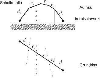 Figure 7: Example of a sound path over more than two authoritiy
Parallel diffraction edges; negligible edges are only taken into account by x marked multiple diffraction if the path of the diffracted sound, as shown by way of example in FIG. 6, leads over several edges. Sound reduction measures are the acoustic properties for sound insulation and sound absorption according to the state of the art. The shielding measure Dz in any octave band should be the case with single diffraction (d. h. in the case of thin shields) not greater than 20 dB and double-diffraction (d. h. in the case of thick sound screens) of not more than 25 dB.
-
6.6
-
Level increase due to reflective or partially reflecting soundproofing walls (e.g. In the case of glass sales), the reflective or absorbing properties of the soundproofing walls are to be taken into account in the calculation by means of mirror sources or mirror receivers. In addition, the reflections between the reflective soundproofing wall and the superstructure are achieved by reducing the shielding effect according to the equation (Gl. 20). Reflections are taken into account after this installation by incoherent mirror sources. On the ground in the vicinity of the source, they are based on the equation (Gl. 9) is connected to the strength of the original source via a space-angle measure. Reflections on buildings and umbrellas shall be calculated for all octave bands only if each of the following requirements is met:
-
-
-
A geometrical/specular reflection can be constructed, as schematically shown in FIG. 8.
-
-
-
The sound reflectivity of the obstacle surface is greater than ρ = 0.2.
-
-
-
The smallest dimension of the reflector satisfies the following equation (Gl. 27):
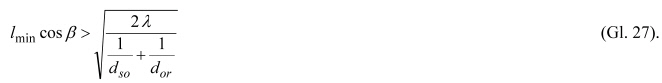 In this case:
| lmin |
the smallest dimension of the reflector, in m, |
| β |
angle between the connection line source to the immission location and the reflector normal, |
 |
sound wave length at the octave band center frequency of the pitch, in m, |
| Dso |
Running path of the sound from the point source Q to the reflector R, in m, |
| dor |
Running path of the sound from the reflector R to the immission location IO, in m. |
 Figure 8: Mirror reflection at an obstacle The A-weighted sound power level of the mirror sound source LWA, is in accordance with the following equation (Gl. 28) to be calculated:
 In this case:
| LWA |
A-weighted sound power level according to the equations (Gl. 7) and (Gl. 8), in dB, |
| Dρ |
Loss of absorption for reflections at the wall surface according to Table 18, in dB, |
| DIr |
The directional measure of the point sound source in the direction of the mirror sound receiver (see equation (Gl. 8)), in dB. |
The frequency dependence of absorption loss and directivity is not taken into account in this system. Table 18: absorption loss on walls
SpalteAB
Time Wall Surface Absorption Loss Dρ in dB
| 1 |
Level and hard walls |
0 |
| 2 |
Building walls with windows and small fittings |
1 |
| 3 |
Absorbent soundproofing walls |
4 |
| 4 |
Highly absorbent soundproofing walls |
8 |
Note on line 1: z. B. tiled support walls, smooth concrete surface. Direct and reflected contributions are determined separately. For mirror sources, the attenuation terms are according to the equation (Gl. 10) as well as Dρ and DIr according to the equation (Gl. 28) in accordance with the propagation path of the reflected sound. These are reflections up to and including the 3. Order to be calculated.
-
7.
-
Calculation of the sound emission The acoustic emission at an immission location is calculated as the equivalent continuous sound pressure level LpAeq for the period of a full hour: It is formed by energetic addition of the contributions by
-
-
-
all subsonic sources in octave bands with centre frequencies from 63 Hz to 8 000 Hz,
-
-
-
all height ranges h,
-
-
-
all parts of kS,
-
-
-
all faces kF and
-
-
-
all propagation paths w.
On tracks of the railway and tramway, summaries of the sound pressure levels are according to the following equation (Gl. 29):
 In this case:
| T |
counter for octave band, |
| h |
Height counter, |
| kS |
Counter for part or a portion thereof, |
| W |
Counter for different propagation paths, |
| LWA, f, h, kS |
A-weighted sound power level of the point sound source in the middle of the part kS, which indicates the emission from the height range h according to the equation (Gl. 6), in dB, |
| DI, kS, w |
Direction measure for the propagation path w according to the equation (Gl. 8), in dB, |
| DΩkS |
Space-angle measure according to the equation (Gl. 9), in dB, |
| Af, h, kS, w |
The propagation attenuation measure in the octave band in the height range h from the section kS along the path w according to the equation (Gl. 10), in dB. |
At Rangier and transhipment stations, summation of the energy takes into account the equations (Gl. 3), (Gl. 4) and (Gl. 7):
 In this case:
| R |
Index for the marshalling yard, |
| T |
counter for octave band, |
| h |
Height counter, |
| I |
Counter for point sound sources, |
| kS |
Part count, |
| kF |
Face Count, |
| W |
Propagation path count, |
| LWA,', h, i |
A-weighted sound power level of the point sound source i according to the equation (Gl. 3), in dB, |
| LWA, f, h, kS |
A-weighted sound power level of the part kS according to the equation (Gl. 6), in dB, |
| LWA, f, h, kF |
A-weighted sound power level of the face kF according to the equation (Gl. 7), in dB, |
| DΩ |
Space-angle measure according to the equation (Gl. 9), in dB, |
| Aj, w |
The propagation attenuation measure in the octave band is along the path w according to the equation (Gl. 10), in dB. |
-
8.
-
Assessment Level
-
8.1
-
Equivalent permanent sound pressure level in assessment periods, the volumes of traffic as a total of the assessment periods (16 hours), which are relevant in accordance with Article 4 (1), second sentence, are the total volume of traffic. At night (8 hours), these traffic volumes are to be converted to mean volumes per hour for these periods. The equivalent continuous-sound pressure levels are calculated according to the equation (Gl. 29) and the equation (Gl. 30) calculated and used for railway and tram routes with Lp, Aeq, Tag, Lp, Aeq, Nacht and/or for Rangier and transhipment stations with Lp, Aeq, Day, R, Lp, Aeq, Night, R designnet.Liegen the volumes are available separately for each hour during the assessment period, the equivalent permanent sound pressure levels for the assessment period are day and for the Evaluation period Night according to the following equations (Gl. 31) and (Gl. 32):
 In this case:
| T |
Count for full hours of the assessment period (6 am to 10 pm), |
| N |
Count for full hours of the evaluation period night (10 p.m. to 6 a.m.). |
-
8.2
-
Assessment level for railways
-
8.2.1
-
Distance An immission site affected by noises from a railway line with or without train stations, stops or stops shall be separated from the assessment level in accordance with Article 4 (1), second sentence, for the assessment period (6 o'clock) until 10 p.m.) and the assessment period of night (22 o'clock to 6 o'clock) according to the following equations (Gl. 33) and (Gl. 34) calculated:
 In this case:
| Lr, day |
Assessment level for the assessment period (6 a.m. to 10 p.m.), in dB, |
| Lr, Night |
Assessment level for the assessment period of night (10 p.m. to 6 p.m.), in dB, |
| Lp, Aeq, Day, Lp, Aeq, Night |
Equivalent continuous sound pressure level of lines, in dB, |
| KS = -5 dB |
Level correction road-rail according to point 2.2.18. |
Level corrections for sound, pulse or information-shale noises are included in the calculation of the noise emission and are not separately applied in the formation of the assessment level. For comparison with the immission limits according to § 2 are the assessment level Lr, day and Lr, to round up to whole dB night. In the case of Section 1 (2) (2), only the difference of the judgment level shall be rounded up.
-
8.2.2
-
Courting and transshipment stations In accordance with Article 4 (1), second sentence, the assessment level shall be separated for the day of assessment (day 6) at a place of immission affected by noises from a railway station or transhipment station as well as railway lines. The following equations (Gl.: Clock until 10 p.m.) and the evaluation period: night (22 o'clock to 6 o'clock) according to the following equations 35) and (Gl. 36) calculated:
 In this case:
| Lr, day |
Assessment level for the assessment period (6 a.m. to 10 p.m.) for the assessment period,
in dB, |
| Lr, Night |
Assessment level for the assessment period of night (10 p.m. to 6 p.m.), in dB, |
| Lp, Aeq, Tag, R, Lp, Aeq, Night, R |
Equivalent continuous sound pressure level from the area of the rangout or transshipment station, in dB, |
| Lp, Aeq, Day, Lp, Aeq, Night |
Equivalent continuous sound pressure level from the range of continuous stretch lines, in dB, |
| KS = -5 dB |
Level correction road-rail within the meaning of point 2.2.18 (does not apply to trains and manoeuvrability travelling in and out of the country). |
Level corrections for sound, pulse or information-shaking noises are not set separately. Such corrections are included in the sound emission. For comparison with the immission limit values according to § 2, the assessment levels Lr, Tag and Lr are to be rounded up to entire dB. In the case of Section 1 (2) (2), only the difference of the judgment level shall be rounded up.
-
8.3
-
Roadway assessment level An immission site affected by noise from a tramway line shall be separated from the assessment level in accordance with Article 4 (1), second sentence, for the assessment period (6 a.m. to 10 p.m.) and the Assessment period of night (22 o'clock to 6 o'clock) according to the following equations (Gl. 37) and (Gl. 38) calculated:
 In this case:
| Lr, day |
Assessment level for the assessment period (6 a.m. to 10 p.m.), in dB, |
| Lr, Night |
Assessment level for the assessment period of night (10 p.m. to 6 p.m.), in dB, |
| Lp, Aeq, Day, Lp, Aeq, Night |
Equivalent continuous sound pressure level of lines, in dB, |
| KS = -5 dB |
Level correction to take into account the reduced interference effect of rail traffic noise in relation to road traffic, in accordance with point 2.2.18. |
Level corrections for sound, pulse or information-shallow noises are included in the calculation of the noise emission and are not separately scheduled for the formation of the assessment level (see point 4.9). The regulations according to § 43 (1) sentence 2 and 3 of the Federal Immission Protection Act as amended on July 12, 2013 remain untouched. For comparison with the immission limit values according to § 2, the assessment level Lr, day and Lr, night at whole dB round. In the case of Section 1 (2) (2), only the difference of the judgment level shall be rounded up.
-
9.
-
Consideration of deviating railway technology and sound-technical innovations
-
9.1
-
Metrological determination of emission data from different railway technology and of sound-technical innovations
-
9.1.1
-
Vehicle The detection of sound-technical innovations in vehicle units shall be carried out in accordance with the following measures: The sound emissions of such vehicle units shall be determined by means of passing measurements on a sill track and stand measurements according to DIN EN ISO 3095 :2014-7, Acoustics-Railway applications-Measurement of noise emissions from track-bound vehicles (ISO 3095 :2014-7); German version EN ISO 3095 :2014-7, taking into account the additional measurement requirements of the decision 2008 /232/EC of the Commission of 21 February 2008 on technical Specification for the interoperability of the 'Vehicles' subsystem of the trans-European high-speed rail system (notified under document number C (2008) 648) (OJ C 348, 28.8.2008, p. 132) (TSI) for railways and VDV-type154 Noise of public passenger rail vehicles-local transport (public transport), November 2011 for trams. The passing measurements should have been carried out after at least three service braking. Note 1: Results of measurements which have already been carried out for other reasons, such as those for example, may be used. B. in the context of the approval of new interoperable rolling stock by Commission Decision 2008 /232/EC, or of trams according to VDV-type154, or emissions data. Note 2: In special cases, the application of directional microphones or an array measurement technique for the detection of individual sound sources may be appropriate. Note 3: Sound technical innovations can be reduced or higher sound emissions than the technology regulated in this system. Higher sound emissions may, for example, by faster high-speed trains, more tractive locomotives, or even older, imported railway technology or tramway technology. The results of the travel measurements are for the maximum speed of regular traffic to be calculated by computer on contributions from
-
-
-
rolling noises,
-
-
-
aerodynamic noises (only for railways),
-
-
-
aggregate noise,
-
-
-
drive noises and
-
-
-
Driving noises (trams only).
For this purpose, data are provided for levels of the A-weighted sound power in the eight octave bands with a mean frequency of from 63 Hz to 8 000 Hz, based on a length of 100 km. If not through stand measurements and special measurements, e.g. The noise emission data for aerodynamic noises, aggregate and drive noises for the vehicle type assigned according to supplement 1 or leaflet 2 are known, for example, behind a sound screen, with a directional microphone or in the wind tunnel, for the vehicle type assigned in accordance with the supplement 1 or the leaflet 2. Note 4: For example, if a V-locomotive is measured at speed v at a distance d in height h over SO in the octave band, there is an A-weighted individual event level LEA, ' and the Measurement of exhaust noises in the stand with the same engine power a sound power level LWA,aggr, taking into account the emission values of the aerodynamic and drive noises as well as of aggregate noise, which occur in addition to the exhaust gas noise according to the single sheet for V-locomotives at speed v-the rolling noise determined on very smooth rails in accordance with the following equation:
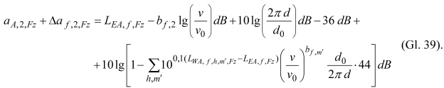 In this case:
| A, 2, Fz |
A-weighted sum level of the length-related sound power at the reference speed v0 = 100 km/h on the threshold of the rolling noise due to the wheel roughness (partial source m= 2), in dB, |
| Δaj, 2, Fz |
Level difference of the length-related sound power at the reference speed v0 = 100 km/h on a threshold for the rolling noise due to the wheel roughness (partial source m= 2), in the octave band, in dB, |
| LEA, |
A-weighted individual event level per octave band, in dB, |
| b, 2 |
Speed factor for rolling noises (subsource m= 2) according to Table 6, |
| C |
Speed during the journey, in km/h, |
| v0 = 100 km/h |
Reference speed, |
| LWA, ',', h, m ', Fz |
A-weighted Oktav sound power level of other subsources, in dB, |
| bj, m ' |
Speed factor for other sub-sources according to Table 6, |
| m ' |
Counter for subsources without m= 2. |
The expression below the sum symbol shall not exceed the value of 0.5 in order to allow for a correction of the noise. The numerical values 36 and 44 are considered to be approximations for distances d from 5 to 10 m.Table 19: Estimation of the emission of the rail roughness (partial source m= 1)
SpalteABC
Time surface condition of the rail Energetic contribution to the total emission level difference to the wheel roughness (Subsource m = 2)
| 1 |
Very smooth |
0% |
-20 dB |
| 2 |
Smooth, limit value according to TSI or VDV 154 |
20% |
-7 dB |
| 3 |
Smooth, limit according to DIN EN ISO 3095 :2014-7 |
40% |
-4 dB |
The rolling noise is to be applied to emissions caused by noise and rail roughness. The following three procedures are admissible for this purpose:
-
a)
-
The measurements were carried out on very smooth rails, but their running surface condition was not measured. The rolling noise emission is then assigned to the vehicle alone (see row 1 of Table 19).
-
b)
-
The measurements were carried out on smooth rails with a proven running surface condition. Then, according to Table 19, an estimation of the emission of the rail roughness is carried out. The remaining contribution to the total emission, but at least 50 per cent of the energy corresponding to a level difference to the wheel roughness of -3 dB, is assigned to the vehicle. This is the rule case.
-
c)
-
In justified exceptional cases and for trams, measurements taken on rails with an unknown surface condition may be used. Then energetically equal contributions of wheel and rail roughnesses are to be assumed.
The procedure referred to in point (c) shall not be applied to vehicles with grey cast iron knock brakes. Note 5: For vehicles alone, the emission-related emission of interest is of interest. It may be determined for rails with good surface condition by up to 3 dB higher according to the procedure referred to in point (a) than in accordance with the procedure referred to in point (c), while the method referred to in point (b) is in the midfield. According to the three methods, measurements on rails with a poor running surface state usually inadvertently supply high emission values due to noise. The rail roughness-related emission is taken over from the leaflets 1 to 3 for the associated vehicle type. For emission-related emissions, measurement results are preferably to be used in accordance with the procedure referred to in point (b). Note 6: The measurement results may be independent of limit values for emission data according to Commission Decision 2008 /232/EC for Railway and VDV-font 154 for trams are used. However, it can be assumed for new vehicles that the limit values are not exceeded. The results for the emission-related emission are to be provided for conversion to the average operating condition with a surcharge, which shall be: Table 20 depends on the measurement conditions. Note 7: The surcharges have been estimated from experience values for the dispersion of measurement results in a database. Table 20: Allowances for conversion to the average operating condition in the database. Dependence on the measurement conditions
SpalteABCD
Row 1 measurement location, Mean over different Fz, in dB3 measuring locations, Mean over different Fz, in dB1 measurement location (e.g. B. TSI, VDV 154), Mean over same Fz, in dB
| 1 |
Vehicles with disc brakes |
2 |
0 |
3 |
| 2 |
Vehicles with composite knock brakes |
2 |
1 |
4 |
| 3 |
Vehicles with grey cast iron knock brakes |
3 |
2 |
5 |
If the measurements were not carried out on a swell (in the gravel bed), but on another track, the level corrections for the types of road maps shown in Table 7 or 7, respectively, are used in the division of the rolling noise. 15.
-
9.1.2
-
Components of vehicle components The sound emission of a vehicle component as a sound technical innovation to an already regulated vehicle category is compared with the sound emission of partial sources of existing vehicles (see Tables 5 and 13). Column D (1) and (2) to be assessed and assessed. For this purpose, measurements must be carried out prior to the detection, from which measurements a decisive contribution of the component can be derived. A contribution which is at most 3 dB lower than the measured value for the total noise shall be considered to be decisive. Measurements according to DIN EN ISO 3095 :2014-7 or special measurements-e.g. Note: For high-lying sources, it is recommended to use measurement results obtained from a shielding wall or with a directional microphone.
-
9.1.3
-
Components of Rangier and transshipment stations The sound emission of a component as a sound technical innovation is to be recorded and assessed in comparison with the sound emission from existing subsources (see Table 10 and Supplement 3). For this purpose, measurements must be carried out prior to the detection, from which measurements a decisive contribution of the component can be derived. A contribution which is at most 3 dB lower than the measured value for the total noise shall be considered to be decisive. The measurements shall be described.
-
9.1.4
-
Roadway deviating railway technology and sound-technical innovations on roadways include, for example, the stiffness of the rail fastening or a better absorption property of the roadway. They shall be recorded and assessed in comparison with known roadways of a similar type, in Tables 7 and 15, in the case of operation of the same vehicles. The emissions shall be determined by means of pre-accession measurements in accordance with DIN EN ISO 3095 :2014-7 under conditions in which the rolling noise predominates. Special testing of the wheel and rail surfaces shall ensure that the resulting surface roughness in the wavelength range, which is to be observed in accordance with Commission Decision 2008 /232/EC and VDV specification 154, shall be taken into account in the case of the following: Comparison measurements in octave bands differ by not more than 1 dB. Preferably, a measuring vehicle is used for the comparison measurement, the wheel surfaces of the measuring vehicle being smooth with respect to the rail surfaces. The test will then be limited to the comparable roughness of the rail surfaces of conventional and new types of road. As an alternative, a measuring vehicle with unchanged high surface roughness of the wheels can be used. In this case, it is only necessary to check compliance with a permissible limit value for the surface roughness of the rails in order to ensure that the influence of the rail roughness remains small in the case of comparison measurements of conventional and novel roadways.
-
9.1.5
-
Bridge-like bridges can be distinguished as sound-technical innovations through special constructions of bridge superstructure or sound reduction measures. They shall be recorded and assessed in comparison with known bridges of similar design according to Tables 9 and 16 in the case of the operation of the same vehicles. The emissions shall be determined by means of pre-departure measurements at the bridge and at the subsequent free distance under conditions where the rolling noise predominates. It is the unrated sound pressure level to be determined. Special testing of the wheel and rail surfaces shall ensure that the resulting surface roughness in the wavelength range, which is to be observed in accordance with Commission Decision 2008 /232/EC and VDV specification 154, shall be taken into account in the case of the following: Comparison measurements in octave bands differ by not more than 1 dB. Note: The evaluation of the unrated sound pressure level takes into account the annoyance due to low-frequency noise components.
-
9.1.6
-
Noise reduction measures on the track and on the wheel sound reduction measures on track and on the wheel come into consideration both as deviating railway technology and as sound technical innovations. Deviating rail technology can also be used for track maintenance measures such as the particularly monitored track on trams. The sound-technical innovations can lead to a change in rolling noise and are in their effect with the sound source type Rolling noise, sub-sources of rail roughness-or wheel roughness of Tables 5 and 13 in conjunction with sheets 1 and 2. To describe:
-
-
-
direct roughness measurements with implementable transducers,
-
-
-
indirect roughness measurements on board a measuring vehicle,
-
-
-
Passing measurements with a measuring vehicle or
-
-
-
Sound measurements during train passing.
The method used shall be presented with an indication of the period of measurement and the determination of an average over an assessment period. For the detection of changes, the measurement results are to be reported as the overall level of the A-weighted sound power and as level differences in the eight octave bands with center frequencies of 63 Hz to 8 000 Hz.
-
9.1.7
-
Railway-specific noise protection measure in the propagation path screening equipment and similar measures, the effect of which cannot be calculated in accordance with point 6.5, shall be described as deviating path technology in association with the existing regulations. For the detection of changes, measurement results in the eight octave bands with center frequencies of 63 Hz to 8 000 Hz are to be indicated as level differences for the calculated shielding dimension according to point 6.5.
-
9.1.8
-
Recognised measuring stelleThe applicant shall have the detection measurements carried out in accordance with points 9.1.1 to 9.1.7 carried out by a recognised measuring point. Recognised measuring points are the bodies announced in accordance with Section 29b (2) of the Federal Immission Protection Act.
-
9.2
-
Evaluation of measurement results for different railway technology and for sound technical innovations
-
9.2.1
-
Deviating railway technology The recognised measuring point shall determine, on the basis of the measurements referred to in point 9.1, which sound technical deviations are to be found to the known railway technology of a similar type, which is listed in Appendix 2. In the case of roadways in accordance with point 9.1.4, the result is indicated as a level correction with respect to the road of similar construction in the octave bands by 500 Hz, 1000 Hz and 2 000 Hz. The remaining octave bands remain unaccounted for; no level correction is given for them. In the case of sound reduction measures on the track or on the wheel according to point 9.1.6, the measurement results shall be the total level of the A-weighted sound power and as level differences in the eight octave bands with centre frequencies of 63 Hz for the detection of changes. up to 8 000 Hz. In the case of deviating railway technology, level differences are the emission of comparable sub-sources described in the leaflets 1 to 3. In the case of railway-specific sound-protection measures in the propagation path according to point 9.1.7, measurement results in the eight octave bands with center frequencies of 63 Hz to 8 000 Hz are used as level differences for the calculated shielding dimension for the detection of changes in the eight octave bands. Number 6.5.
-
9.2.2
-
Sound-technical innovation The recognised measurement point shall, on the basis of the measurements referred to in point 9.1, determine whether the subject-matter of the application is substantially different from the sound technical information provided by this Appendix. sound technical innovations referred to in points 9.1.1 to 9.1.6, if for a sub-source according to Table 5 or 13 the deviation in the A-weighted total level for the individual vehicle garden according to Table 3 or 12 at least 2 dB, or at least 4 dB in individual octave bands. In the case of a sound protection measure in the propagation path according to point 9.1.7, there is usually a significant deviation from the calculation results according to point 6 if the deviation for the calculation result at an immission location according to DIN EN ISO 3095 :2014-7 in the A-weighted total level, at least 2 dB or in individual octave bands at least 4 dB. The recognised measuring point has for all sound technical innovations the assignment of the subject of the application to the existing leaflets or stipulations to describe in points 3 to 6 and the different sound-technical effects . The sound-technical effect shall be carried out by the verification of whole dB by mathematical rounding. In the case of sound technical innovations according to points 9.1.1, 9.1.2 and 9.1.3, the results shall be the total level of the A-weighted sound power and as a To indicate level differences in eight octave bands with centre frequencies of 63 Hz to 8 000 Hz for the reference speed of 100 km/h in accordance with the leaflets 1 to 3. Characteristic of sound technical innovations are level differences for the emission of comparable partial sources described in the leaflets 1 to 3. In the case of sound-technical innovations according to point 9.1.4, the result is compared with the level correction. of the track of similar construction in the octave bands by 500 Hz, 1 000 Hz and 2 000 Hz. The remaining octave bands remain unaccounted for; no level correction is specified for them. In the case of sound technical innovations according to point 9.1.5, the result is as level correction KBr or for sound reduction measures as level correction KLM. , which results from the difference between the unrated sound pressure levels at the bridge and the free distance.
-
9.3
-
Opinion of the recognised measuring stelleThe recognised measuring point referred to in point 9.1.8 of the applicant shall draw up an expert opinion on the measurements carried out in accordance with points 9.1.1 to 9.1.7, which shall include the following information and documents must be included:
-
a)
-
the description of the measurement setup,
-
b)
-
the description of the local conditions and the description of the condition of the track and of the rail surfaces,
-
c)
-
the description of meteorological conditions,
-
d)
-
the description of the state of entertainment, the mileage and the roughness of the vehicle used in the measurement,
-
e)
-
the measurement protocols of the measurements carried out;
-
f)
-
an indication of the number of measurements carried out when more than the measurements taken in the assessment have been carried out,
-
g)
-
the evaluation of the measurement results in accordance with point 9.2.
-
10.
-
Accessibility of technical rules and standards
-
1.
-
The DIN standards, DIN EN standards and DIN ISO standards referred to in the regulation are to be obtained from Beuth Verlag GmbH, Berlin, and are deposited in the German National Library in an archive-based way.
-
2.
-
The VDV-font 154 is to be obtained by the German Transport Companies Association (VDV)
Kamekestraße 37-39
50672 Cologne
and in the German National Library (German National Library), secured in the archive.
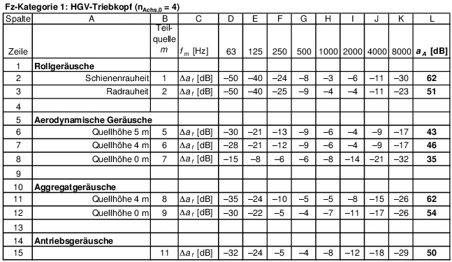
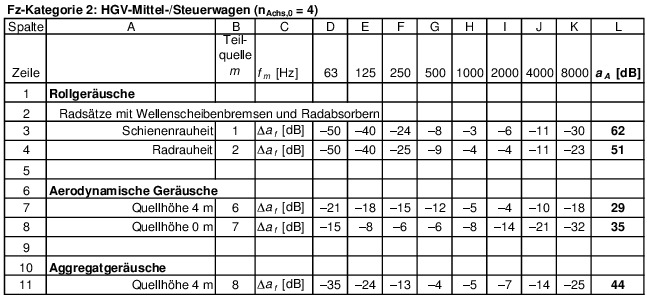
For the Thalys-PBKA half-train and Thalys-PBKA-full train without wheel absorber :A of the sub-sources 1 and 2 are to be increased by 5 dB each.
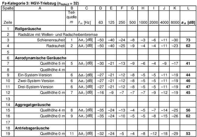
For the ETR 470 Cisalpino without wheel absorber: A of the sub-sources 1 and 2 are to be increased by 5 dB each, all further subsources by 2 dB each.
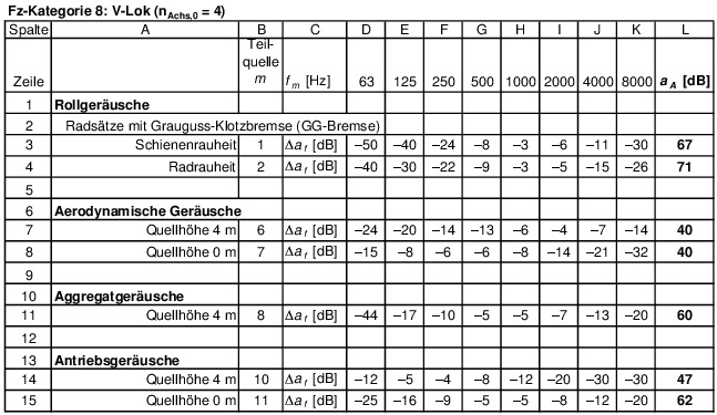
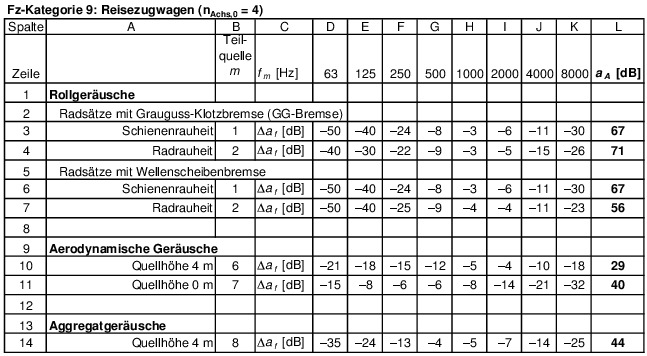
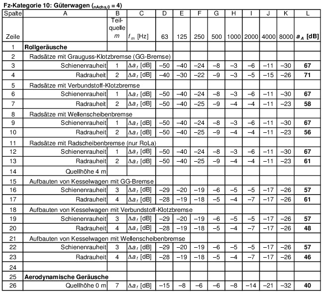
Leaflet 2 Datasheets Trams-Festinterpretations
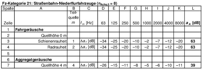
For vehicles with climate contact: A of the sub-source 4 is to be increased by 8 dB.
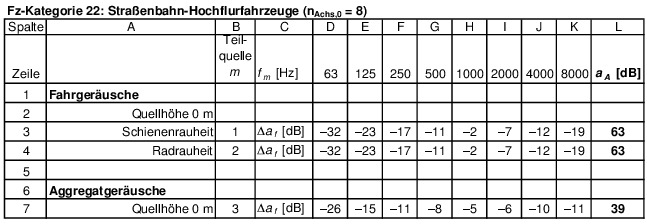
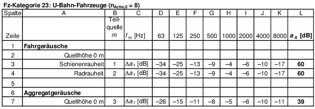 The specified values apply to the average new type of vehicles. In particular in the case of older vehicles, a review in accordance with section 9.1.1 is required.
Leaflet 3 Data sheets Rangier and transshipment stations-Stations
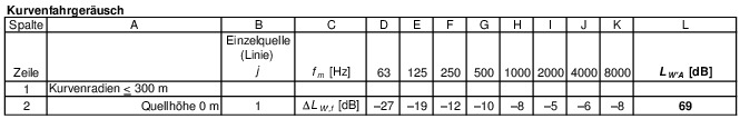
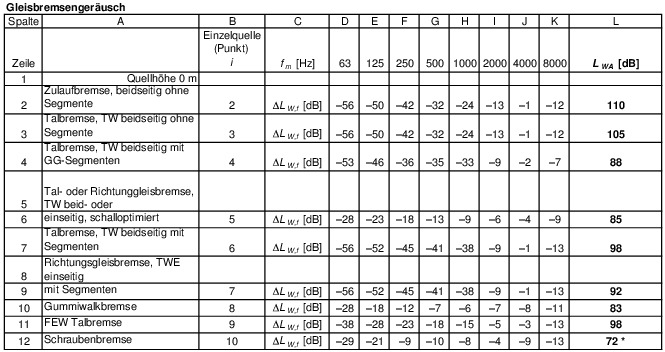
* The specified LWA is valid for a braking element with the length of approx. 1.2 m.
* nret is the number of retarder per running meter track.
* nret is the number of retarder per running meter track.
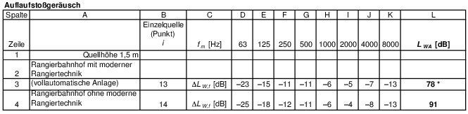
* The run-up speed must not exceed v = 1.25 m/s.
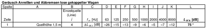 * The value refers to a shunting group of 20 cars (400 m in length).